Waves, sound and light: Identify and critically evaluate the impact of geometrical optics on human development
Unit 1: Converging and diverging lenses
Dylan Busa
Unit outcomes
By the end of this unit you will be able to:
- Construct and interpret diagrams of an image formed by a converging (convex) lens.
- Construct and interpret diagrams of an image formed by a diverging (concave) lens.
What you should know
Before you start this unit, make sure you can
- Identify light as a transverse wave.
- Identify and describe the wave properties of light including reflection and refraction.
- Draw diagrams showing reflection, angle of incidence and angle of reflection using plane, concave and convex mirrors and the type, size and distance of the image formed.
- Describe what a ray diagram is and draw a ray diagram.
Refer to level 2 subject outcome 3.2 units 1 and 2 if you need help with any of these concepts.
Introduction
Some people wear glasses to help them read. While you might not wear glasses now, it is likely that, as you grow older, you too will need glasses to help you see the world more clearly. Some people need glasses to help them see things that are close. Others need glasses to help them see things that are far away. Still others need both types.
In this unit, we will use what we know about how light behaves to learn about the principles that govern the behaviour of light through different types of lenses. A lens is a piece of glass or other transparent material with curved sides for focussing or dispersing light rays. All lenses have a focal point – a point at which the light rays meet. The position of this focal point determines the kind of image that the lens forms.
Lenses are commonly used in glasses, also called spectacles, magnifying glasses, microscopes and telescopes.
In this unit we will learn how to draw ray diagrams that show how a specific lens focusses or disperses light rays and to determine where the focal point is. Understanding how to draw and interpret such ray diagrams will serve as the basis for understanding the applications of lenses later.
Types of lenses
There are two basic types of lenses that we will deal with – converging lenses and diverging lenses.
Converging (convex) lenses
A converging lens, as the name suggests, is a piece of specially shaped glass that has the effect of making light rays entering the lens on one side to converge (or meet) at a single point on the other side of the lens. They achieve this by being convex in shape. You learnt about convex mirrors in level 2 subject outcome 3.2. These lenses bulge out in the middle (see figure 1).
Note
Because both sides are curved, these lenses are also sometimes called double or biconvex lenses.

An ordinary magnifying glass is an example of a converging (convex) lens (see figure 2).

The point at which parallel light rays converge on one side of the lens is called the focal point (sometimes also called the principal focus). The position of the focal point (shown in figure 3) depends on the curvature of the lens. The distance from the middle of the lens to the focal point is called the focal length.
The more curved the lens is, the closer the focal point is to the lens, the shorter the focal length is, and the more powerful the lens is said to be. In simple terms, the power of a lens is a measure of the extent to which the lens converges or diverges the light. The more powerful a lens is, the more it can converge or diverge light.
We learnt in level 2 subject outcome 3.2 that we can use ray diagrams to model how mirrors converge and diverge light and to describe the kind of image that is formed. We can use ray diagrams with lenses in the same way.
Figure 3 is a ray diagram showing how a converging lens converges light to the focal point.

Diverging (concave) lenses
A diverging lens, as the name suggests, is a piece of specially shaped glass that has the effect of making light rays entering the lens on one side diverge or spread out from each other on the other side of the lens. They achieve this by being concave in shape. They curve inward in the middle (see figure 4).
Note
To help you remember the name you can think of the shape as resembling the inside of a cave. Because both sides are curved, these lenses are also sometimes called double concave or biconcave lenses.
As with converging lenses, diverging lenses also have a focal point. However, this is the point at which the diverging rays meet if we continue them with imaginary lines (see figure 5).

Ray diagrams for converging lenses
We know that a converging lens will make the light rays entering from one side of the lens converge at the focal point on the other side of the lens. But how do they do this and what kind of image do they create? We draw ray diagrams to determine the location, size, orientation, and type of image formed. When drawing ray diagrams for convex lenses, we need to remember the three rules of refraction for convex lenses.
The three rules of refraction for converging (convex) lenses
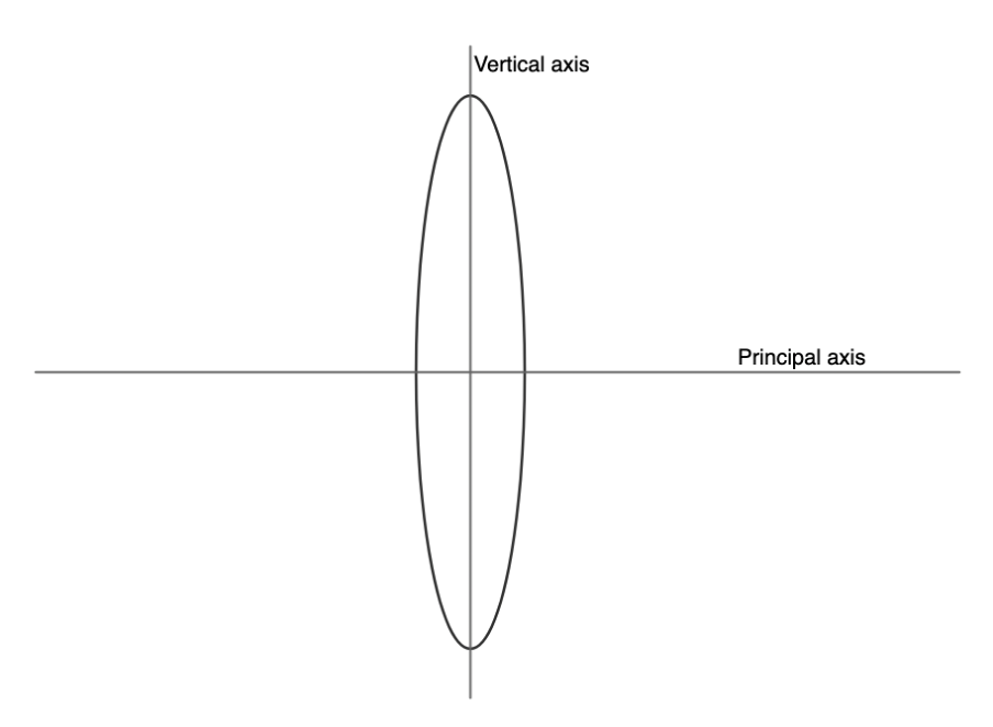
To discover these rules, there are two important lines we first need to label – the principal axis and the vertical axis (see figure 6). Where these axes meet is called the optical centre of the lens.
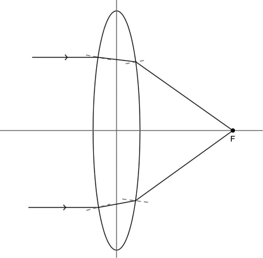
Now, suppose that two light rays travel parallel to the principal axis of the lens. Upon reaching the front face of the lens, the rays will refract towards the at the surface because, at this boundary, they pass from air into a more dense medium (usually plastic or glass). Since the rays pass from a less optically dense medium to a more optically dense medium, they slow down and bend towards the normal (see figure 7). The rays then travel in a straight line until they reach the back face of the lens. At this boundary, the rays refract away from the normal to the surface because they are passing from a more optically dense medium to a less optically dense medium and speed up. They bend away from the normal line (see figure 7). The result is that the light rays converge at the focal point.
Note
Any travelling parallel to the principal axis of a converging lens will refract and travel through the focal point of the lens on the opposite side of the lens.
The above situation also happens in reverse. Any light ray travelling through the focal point on the way to the lens will be refracted to emerge from the other side of the lens to run parallel to the principal axis.
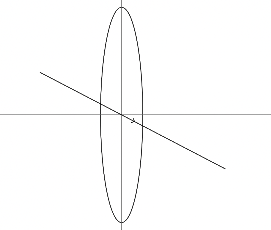
The final behaviour of a light ray we need to consider is that of a ray that passes through the optical centre of the lens where the principal and vertical axes meet. These rays refract in such a way that they pass directly through the lens in a straight line (see figure 8).
Take note!
An incident ray that passes through the centre of the lens will, in effect, continue in the same direction that it had when it entered the lens.
To draw a ray diagram for a converging (convex) lens:
- Any incident ray travelling parallel to the principal axis of a converging lens will refract through the lens and travel through the focal point on the opposite side of the lens.
- Any incident ray travelling through the focal point on the way to the lens will refract through the lens and travel parallel to the principal axis on the opposite side of the lens.
- An incident ray that passes through the optical centre of the lens will, in effect, continue in the same direction that it had when it entered the lens.
Let’s put these rules to work by drawing a ray diagram for an object that is more than twice the focal length away from the lens.
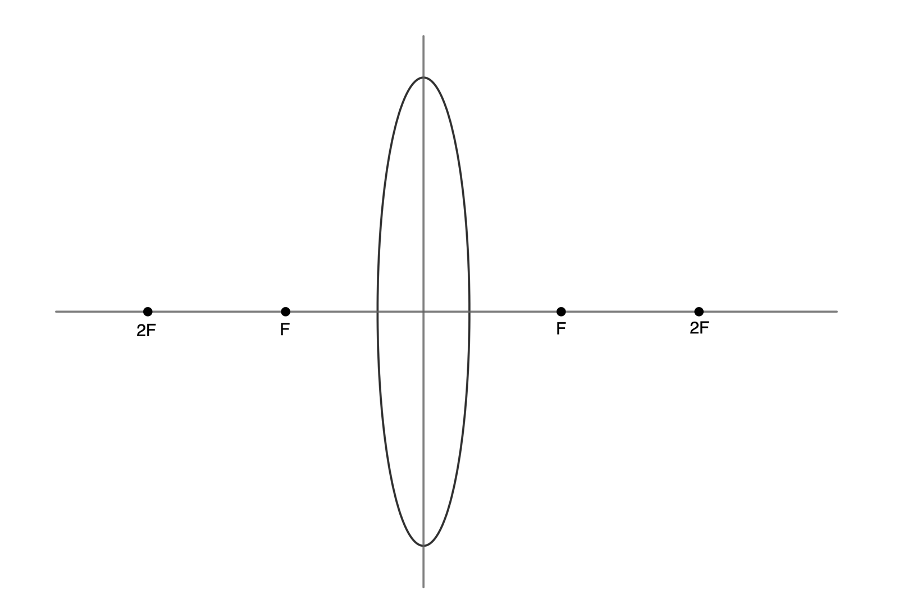
Step 1: Draw the lens, the principal axis and the vertical axis. On the principal axis, mark the focal point of the lens on both sides of the lens as [latex]\scriptsize F[/latex]. Also mark the points [latex]\scriptsize 2F[/latex] – the points representing twice the focal length (see figure 9).
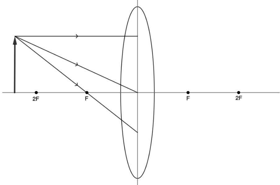
Step 2: Place the object in the necessary position on the principal axis. In this case the object must be more than twice the focal distance away from the lens. From the top of the object draw three incident rays travelling towards the lens. One of these rays must travel parallel to the principal axis. Another must travel through the focal point. The third must travel through the centre of the lens (see figure 10).
Note
Ray diagrams can be created for objects which do not lie on the principal axis, but this is not a case that you will need to draw.
Step 3: Refract each of the incident rays according to the rules of refraction for convex lenses (see figure 11). The ray travelling parallel to the principal axes passes through the focal point on the other side of the lens. The ray travelling through the focal point, emerges to run parallel to the principal axis. The ray travelling through the centre of the lens continues in the same straight line.
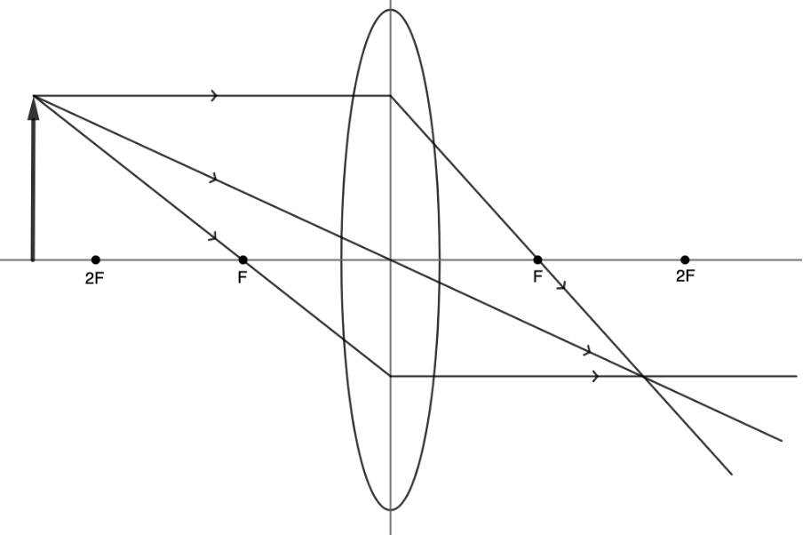
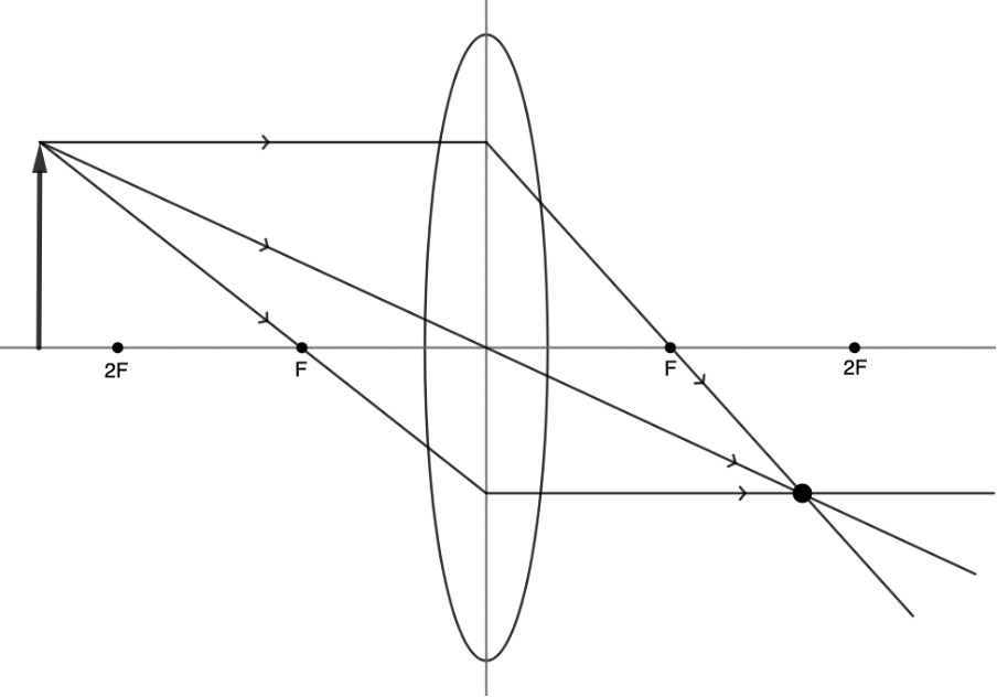
Step 4: Where the three refracted rays meet is the location of the top of the image (see figure 12). Mark this point. Remember that this is just the image of the top of the object and that the rest of the object has an image as well.
Step 5: Repeat the same process for the bottom of the object to find its image. If the bottom of the object is on the principal axis (as in this case), then the image of the bottom will also lie on the principal axis the same distance away from the lens as the image of the top of the object. We can now draw in the full image (see figure 13).
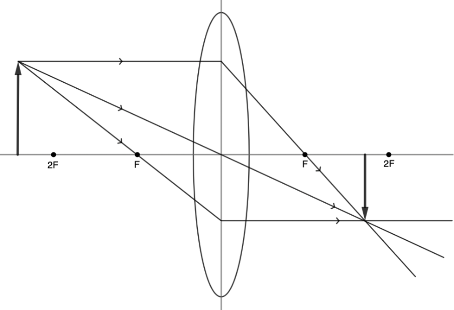
Our ray diagram reveals that when an object is more than twice the focal length away from a converging lens the image formed is:
- real – it can be projected
- inverted – it is upside down
- reduced – smaller than the original
- positioned between [latex]\scriptsize F[/latex] and [latex]\scriptsize 2F[/latex].
Activity 1.1: Draw an image formed by a converging lens
Time required: 45 minutes
What you need:
- a piece of paper
- a pencil
- a ruler
- an internet connection
What to do:
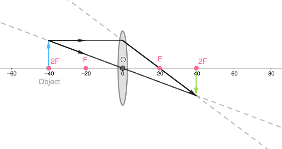
- Draw your own ray diagram to find out what kind of image is formed if an object (a vertical arrow with its bottom on the principal axis) is placed at a distance of [latex]\scriptsize 2F[/latex] from a converging lens.
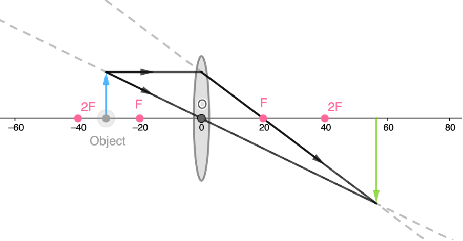
- Draw your own ray diagram to find out what kind of image is formed if an object (a vertical arrow with its bottom on the principal axis) is placed at a distance between [latex]\scriptsize F[/latex] and [latex]\scriptsize 2F[/latex] from a converging lens.
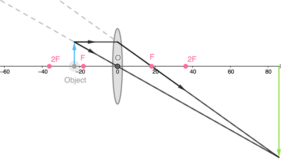
- Draw one or more ray diagrams to see what happens to the magnification and the position of the image as the object is moved closer to [latex]\scriptsize F[/latex].
- Draw your own ray diagram to find out what kind of image is formed if an object (a vertical arrow with its bottom on the principal axis) is placed at a distance of [latex]\scriptsize F[/latex] from a converging lens.
- Draw your own ray diagram to find out what kind of image is formed if an object (a vertical arrow with its bottom on the principal axis) is placed at a distance less than [latex]\scriptsize F[/latex] from a converging lens.
- Draw one or more additional ray diagrams to see what happens to the placement of the image as the object is placed beyond [latex]\scriptsize 2F[/latex] and further and further away from the lens, potentially an infinite distance away.
- If you have an internet connection, you can check your work by using the interactive convex ray diagram simulation.
Here you will be able to change the height of the object as well as the focal length of the lens.
What did you find?
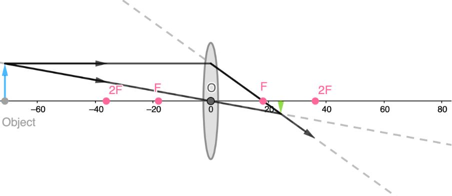
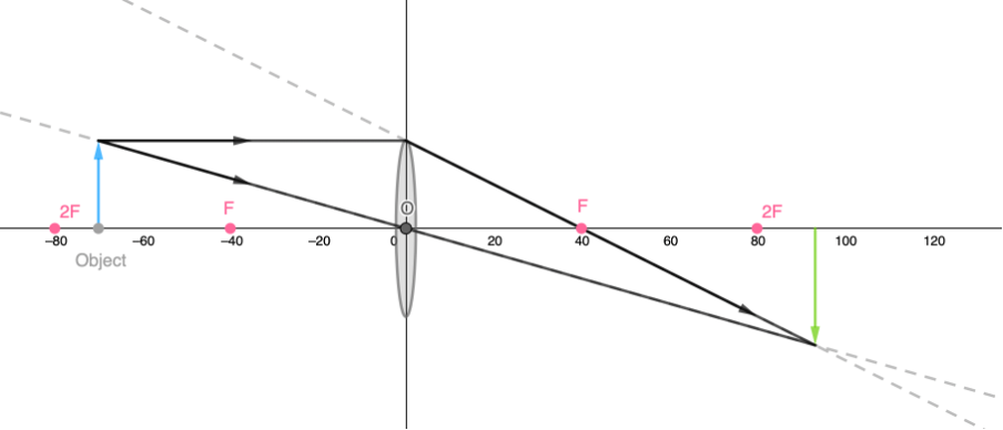
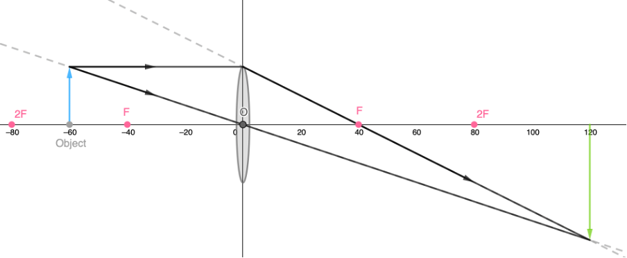
- An object placed at a distance of [latex]\scriptsize 2F[/latex] forms a real, inverted image the same size as the object at a distance of [latex]\scriptsize 2F[/latex].
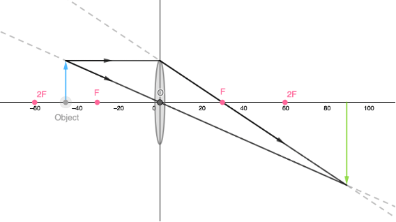
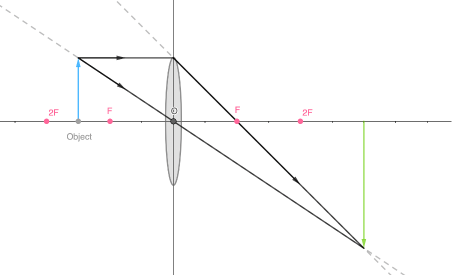
- An object between [latex]\scriptsize F[/latex] and [latex]\scriptsize 2F[/latex] forms a real, inverted, magnified image at a distance greater than [latex]\scriptsize 2F[/latex].
- As we move the object closer and closer to [latex]\scriptsize F[/latex], we can see that the image is formed further and further away from the lens and that the magnification of the image gets greater and greater.
- An object at the focal length forms no image.
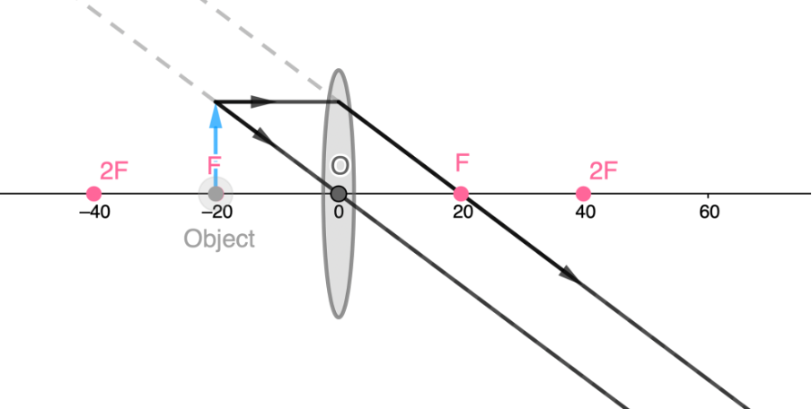
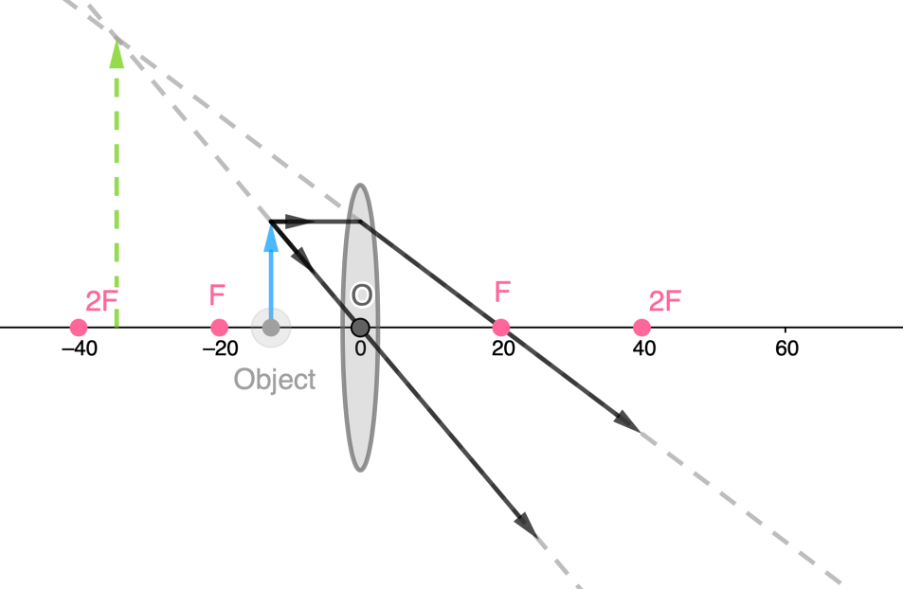
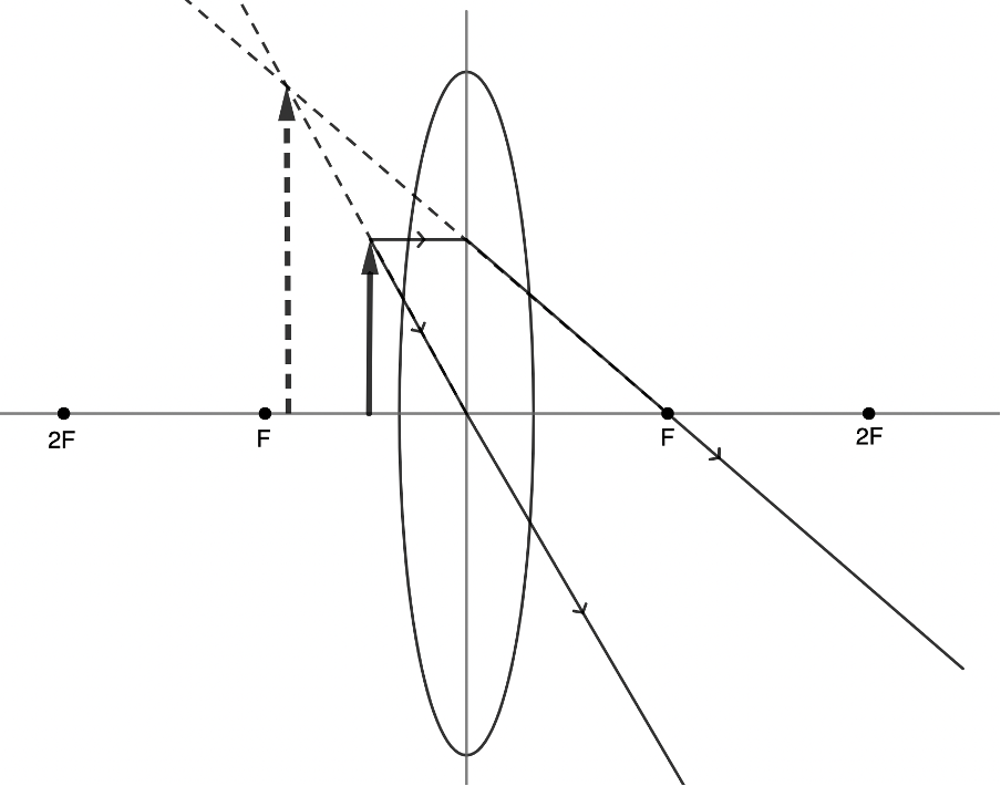
- An object at less then [latex]\scriptsize F[/latex] forms a virtual, non-inverted, magnified image on the same side of the lens at a distance greater than the distance of the object from the lens.
- We know that when an object is placed at [latex]\scriptsize 2F[/latex], an image forms at [latex]\scriptsize 2F[/latex].
However, as we continue to move the object further and further away, we see that the image formed gets closer and closer to [latex]\scriptsize F[/latex]. We can say then that when an object is placed very far away from a convex lens, the image will be formed at the focal point of the lens.
From activity 1.1 we can see that the placement of the object has an effect on the type, placement and size of the image formed.
In the final part of activity 1.1, we also discovered that sometimes the image formed by a convex lens is virtual. This means that the image cannot be projected onto a screen but is rather the image the appears to be formed or the image we perceive to be created. In fact, it is in this situation that magnifying glasses work as magnifying glasses. The image we perceive is not inverted. In other words, it is upright, magnified and seems to be formed on the same side of the lens as the object we are viewing. Because the rays do not converge on the other side of the lens as the object, we have to extrapolate them back using dotted lines until they intersect (see figure 14). We also draw the image with a dotted line to indicate that it is a virtual image.
Take note!
Here is a summary of the object–image relationships for converging lenses.
| Object position | Image position | Image type | Image size | Image orientation |
| Beyond [latex]\scriptsize 2F[/latex] | Between [latex]\scriptsize 2F[/latex] and [latex]\scriptsize F[/latex] | Real | Reduced | Inverted |
| Note: The further away the object is, the closer the image is to [latex]\scriptsize F[/latex]. We can assume that if an object is very far away then the image is formed at [latex]\scriptsize F[/latex] | ||||
| At [latex]\scriptsize 2F[/latex] | At [latex]\scriptsize 2F[/latex] | Real | Same size | Inverted |
| Between [latex]\scriptsize 2F[/latex] and [latex]\scriptsize F[/latex] | Beyond [latex]\scriptsize 2F[/latex] | Real | Magnified | Inverted |
| Note: As the object gets closer and closer to F so the image is formed further and further away from the lens and the magnification is greater and greater. | ||||
| At [latex]\scriptsize F[/latex] | No image | |||
| Between [latex]\scriptsize F[/latex] and lens | In front of [latex]\scriptsize F[/latex] (on the same side as the object) | Virtual | Magnified | Upright (not-inverted) |
Notice how similar this is to the kinds of images formed by converging mirrors that we saw in level 2 subject outcome 3.2 unit 2.
| Object position | Image position | Image type | Image size | Image orientation |
| 1. Beyond [latex]\scriptsize 2F[/latex] | Between [latex]\scriptsize 2F[/latex] and [latex]\scriptsize F[/latex] | Real | Reduced | Inverted |
| 2. At [latex]\scriptsize 2F[/latex] | At [latex]\scriptsize 2F[/latex] | Real | Equal to size of object | Inverted |
| 3. Between [latex]\scriptsize 2F[/latex] and [latex]\scriptsize F[/latex] | Beyond [latex]\scriptsize 2F[/latex] | Real | Magnified | Inverted |
| 4. At [latex]\scriptsize F[/latex] | No image formed | |||
| 5. Between [latex]\scriptsize F[/latex] and mirror | Behind mirror, at a distance that corresponds to a point between [latex]\scriptsize 2F[/latex] and [latex]\scriptsize F[/latex] | Virtual | Magnified | Upright |
Take note!
The object in all the examples above is just a simple vertical line with its bottom on the principal axis. The same process can be applied to any object in any orientation positioned anywhere in front of the lens. However, in these non-simple cases, it is necessary to repeat the process above for each point on the object. You will only be expected to draw ray diagrams of this simplified case. Click here to experiment with a simulation of this simple case.
You will also have noticed that in figure 6 and all the ray diagrams in activity 1.1, we did not draw the incident ray that passes through the focal point of the lens and emerges parallel to the principal axis. In the simple case of a vertical object resting on the principal axis, we only need to draw two of the possible three rays in order to define the type and position of the object. In principle, you can choose to draw any two of the standard three rays, however, not drawing the ray passing through the optical centre of the lens is common practice.
As soon as the object is not on the principal axis, the third ray becomes essential to include.
Ray diagrams for diverging lenses
The same three basic rules of refraction apply to a diverging or convex lens with a few modifications.
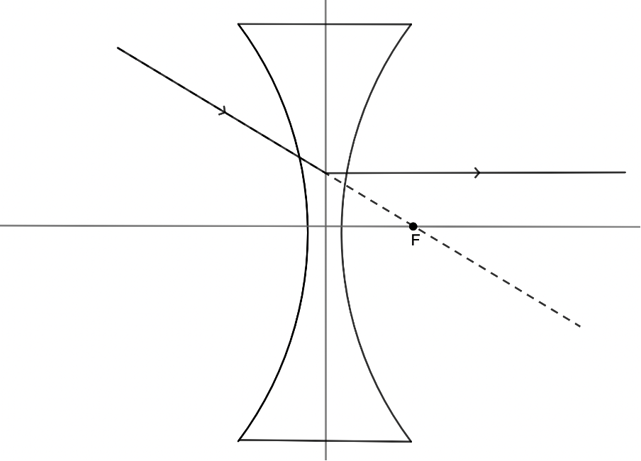
Any incident ray travelling parallel to the principal axis of a diverging lens will refract through the lens and travel in line with the focal point (i.e. in a direction such that its extrapolation will pass through the focal point) (see figure 15).
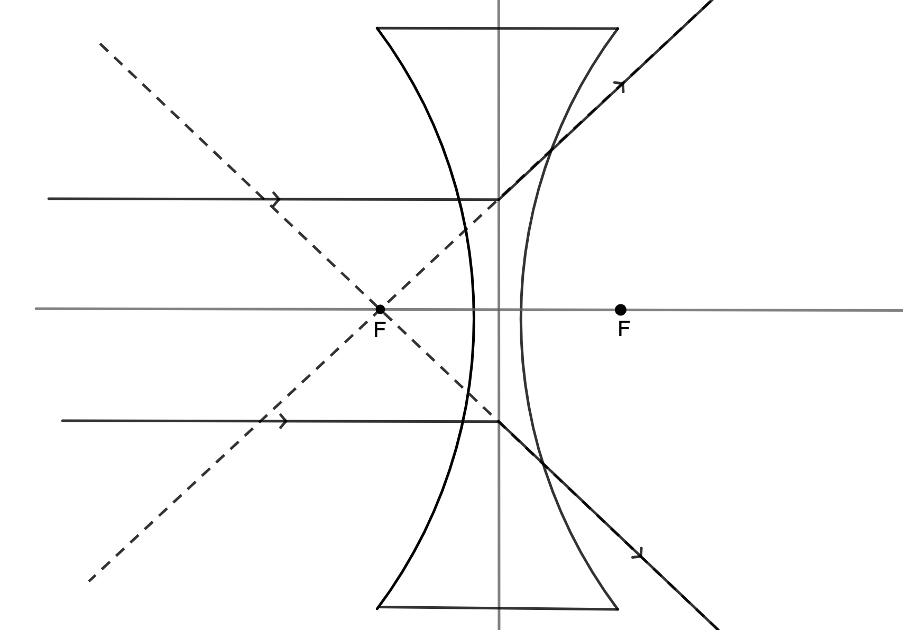
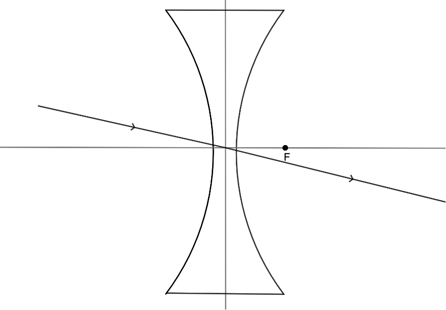
Any incident ray travelling towards the focal point on the way to the lens will refract through the lens and travel parallel to the principal axis (see figure 16).
An incident ray that passes through the optical centre of the lens will, in effect, continue in a straight line (see figure 17).
Draw a ray diagram for a concave lens
We use the same process to draw ray diagrams for diverging lenses as we use for converging lenses. Only now we need to apply the slightly modified rules of refraction for diverging lenses.
Activity 1.2: Drawing diverging lens images
Time required: 15 minutes
What you need:
- a piece of paper
- a pencil
- a ruler
- an internet connection
What to do:
- Draw your own ray diagram to find out what kind of image is formed if an object (a vertical arrow with its bottom on the principal axis) is placed at a distance greater than [latex]\scriptsize 2F[/latex] from a diverging lens.
- Draw your own ray diagram to find out what kind of image is formed if an object (a vertical arrow with its bottom on the principal axis) is placed at a distance of [latex]\scriptsize 2F[/latex] from a diverging lens.
- Draw your own ray diagram to find out what kind of image is formed if an object (a vertical arrow with its bottom on the principal axis) is placed at a distance between [latex]\scriptsize F[/latex] and [latex]\scriptsize 2F[/latex] from a diverging lens.
- Draw your own ray diagram to find out what kind of image is formed if an object (a vertical arrow with its bottom on the principal axis) is placed at a distance of [latex]\scriptsize F[/latex] from a diverging lens.
- Draw your own ray diagram to find out what kind of image is formed if an object (a vertical arrow with its bottom on the principal axis) is placed at a distance less than [latex]\scriptsize F[/latex] from a diverging lens.
- If you have an internet connection, you can check your work by using the interactive concave ray diagram simulation.
Here you will be able to change the height of the object as well as the focal length of the lens.
What did you find?
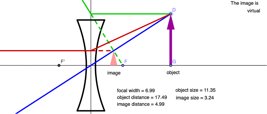
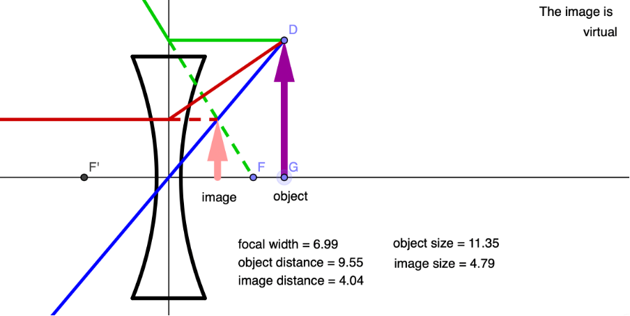
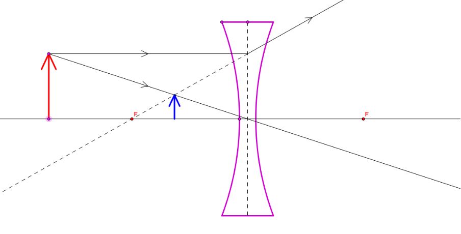
- An object placed at a distance greater than [latex]\scriptsize 2F[/latex] forms a virtual, non-inverted and reduced image at a distance less than [latex]\scriptsize F[/latex] on the same side of the lens as the object.
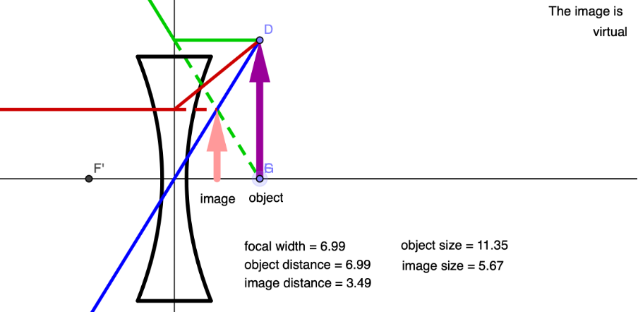
- An object placed at a distance of [latex]\scriptsize 2F[/latex] forms a virtual, non-inverted and reduced image at a distance less than [latex]\scriptsize F[/latex] on the same side of the lens as the object.
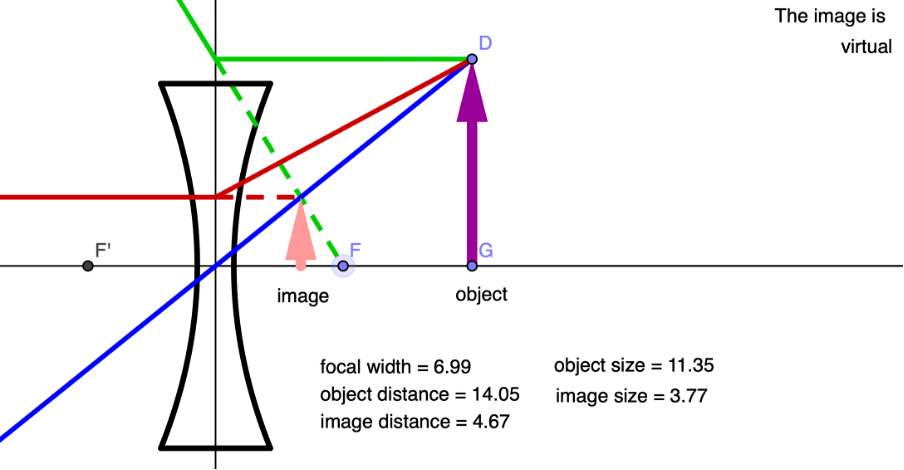
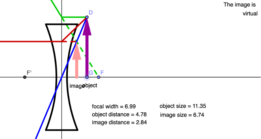
- An object between [latex]\scriptsize F[/latex] and [latex]\scriptsize 2F[/latex] forms a virtual, non-inverted and reduced image at a distance less than [latex]\scriptsize F[/latex] on the same side of the lens as the object.
- An object at the focal length forms a virtual, non-inverted and reduced image at a distance less than [latex]\scriptsize F[/latex] on the same side of the lens as the object.
- An object placed at a distance less than [latex]\scriptsize F[/latex] forms a virtual, non-inverted, magnified image on the same side of the lens at a distance greater than the distance of the object from the lens.
Irrespective of where we place the object, a diverging lens will always form an image that is:
- virtual
- upright (upright)
- reduced
- on the same side of the lens as the object.
However, we can say that as the object distance is decreased, the image distance decreases, and the image gets bigger.
Scale ray diagrams
As we have seen, ray diagrams are useful in determining the kind of image that a lens will form when the object is in different positions. However, if we draw ray diagrams to scale, we can also use them to determine exactly where and how big the image will be. Have a look at the next example.
Example 1.1
A convex lens has a focal length of [latex]\scriptsize 40\ \text{mm}[/latex]. An object, [latex]\scriptsize 20\ \text{mm}[/latex] high, is placed on the principal axis [latex]\scriptsize 70\ \text{mm}[/latex] from the optical centre of the lens.
- Determine the size of the image formed and how far from the optical centre of the lens it is.
- Determine the magnification.
Solution
- The only difference between the ray diagram we need to draw to answer this question and the diagrams we have drawn previously is that this one needs to be drawn to scale. Therefore, the first thing you need to do is to choose an appropriate scale. One possible scale to use is to make [latex]\scriptsize 5\ \text{mm}[/latex] be [latex]\scriptsize 1\ \text{cm}[/latex]. Therefore, the focal length of this lens, on paper, will be [latex]\scriptsize 8\ \text{cm}[/latex].
.
Here is a ray diagram, drawn to scale. We can see that the general object–Image relationship for a converging lens where the object is between [latex]\scriptsize 2F[/latex] and [latex]\scriptsize F[/latex] is correct. The image is:- beyond [latex]\scriptsize 2F[/latex]
- real
- magnified
- inverted.
All we need to do now is measure the length of the image and measure the distance of the image from the optical centre, remembering to convert the distance on paper to the actual distance using our chosen scale. When you do this, you should find that the image is about [latex]\scriptsize 27\ \text{mm}[/latex] in length and [latex]\scriptsize 93\ \text{mm}[/latex] away from the optical centre. - Magnification is just the ratio of the image height to the object height. Because we are dividing one length by another, magnification has no units.
[latex]\scriptsize \text{Magnification}=\displaystyle \frac{{\text{Image height}}}{{\text{Object height}}}=\displaystyle \frac{{27\ \text{mm}}}{{20\ \text{mm}}}=1.35[/latex]
Exercise 1.1
Question adapted from NC(V) Physical Science Level 3 Paper 1 November 2019 question 8.3
A convex lens has a focal length of [latex]\scriptsize 30\ \text{mm}[/latex]. An object, [latex]\scriptsize 20\ \text{mm}[/latex] high, is placed on the principal axis [latex]\scriptsize 45\ \text{mm}[/latex] from the optical centre of the lens.
- Draw an accurate ray diagram to show how the image is formed by this lens.
- Determine the size of the image formed from the diagram.
- Determine the distance of the image from the lens.
The full solutions can be found at the end of the unit.
Summary
In this unit you have learnt the following:
- Converging lenses cause parallel rays to converge at the lens’ focal point.
- Converging lenses are convex in shape.
- Diverging lenses cause parallel rays to diverge, such that the extrapolated lines converge at the lens’ focal point.
- Diverging lenses are concave in shape.
- The position of an object affects the type, size and position of the image formed by a converging lens.
- Diverging lenses always form virtual, reduced, non-inverted images.
- Ray diagrams drawn to scale can be used to determine the image height and distance from the optical centre of the lens.
Unit 1: Assessment
Suggested time to complete: 20 minutes
- What is the difference between a real and a virtual image?
- If the focal length of a lens is [latex]\scriptsize 5\ \text{cm}[/latex] and the object is placed [latex]\scriptsize 7.5\ \text{cm}[/latex] in front of a converging lens:
- What type of image will form?
- Where will the image form relative to the focus point of the lens?
- Construct a ray diagram to illustrate your answer.
- What type of image do you expect to form when an object is placed in front of a diverging lens? Construct a diagram to illustrate your answer.
Question 4 adapted from NC(V) Physical Science Level 3 Paper 1 March 2019 question 8.2
- An object [latex]\scriptsize 2\ \text{cm}[/latex] high is placed [latex]\scriptsize 3\ \text{cm}[/latex] from a convex lens between [latex]\scriptsize F[/latex] and [latex]\scriptsize 2F[/latex]. The lens has a focal length of [latex]\scriptsize 2\ \text{cm}[/latex].
- Determine the size and position of the image formed by this lens through construction and measurement.
- Name any three properties of the image formed by the above lens.
- Calculate the magnification of the image.
- Name one use of a convex lens.
The full solutions can be found at the end of the unit.
Unit 1: Solutions
Exercise 1.1
- .
- The size of the image is about [latex]\scriptsize 39\ \text{mm}[/latex].
- The distance of the image from the optical centre is about [latex]\scriptsize 90\ \text{mm}[/latex].
Unit 1: Assessment
- A real image occurs where light rays converge. A virtual image occurs where light rays only appear to converge but in fact have diverged. To find the location of a virtual image, one needs to extrapolate the diverging rays back to the point where they meet. Real images can be produced by converging lenses but only if the object is placed further away from the lens than the focal point. In this case the real image is inverted.
- If the focal length of a lens is [latex]\scriptsize 5\ \text{cm}[/latex] and the object is placed [latex]\scriptsize 7.5\ \text{cm}[/latex] in front of a converging lens:
- The object is placed between [latex]\scriptsize 2F[/latex] and [latex]\scriptsize F[/latex]. Therefore, a real, magnified and inverted image will be formed.
- The image will form beyond [latex]\scriptsize 2F[/latex].
- .
- A diverging lens will create a virtual, reduced, non-inverted image.
- .
- The image height is [latex]\scriptsize 4\ \text{cm}[/latex]; the image distance is [latex]\scriptsize 6\ \text{cm}[/latex].
- Real, inverted, magnified, beyond [latex]\scriptsize 2F[/latex]
- [latex]\scriptsize \text{Magnification}=\displaystyle \frac{{\text{Image height}}}{{\text{Object height}}}=\displaystyle \frac{{4\ \text{cm}}}{{2\ \text{cm}}}=2[/latex]
- Magnifying glass
- The image height is [latex]\scriptsize 4\ \text{cm}[/latex]; the image distance is [latex]\scriptsize 6\ \text{cm}[/latex].
Media Attributions
- figure1 © Sjlegg is licensed under a Public Domain license
- figure2 © Pxhere is licensed under a CC0 (Creative Commons Zero) license
- figure3 © Kvr.lohith is licensed under a CC BY-SA (Attribution ShareAlike) license
- figure4 © Sjlegg is licensed under a Public Domain license
- figure5 © Kvr.lohith is licensed under a CC BY-SA (Attribution ShareAlike) license
- figure6 © Geogebra is licensed under a CC BY-SA (Attribution ShareAlike) license
- figure7 © Geogebra is licensed under a CC BY-SA (Attribution ShareAlike) license
- figure8 © Geogebra is licensed under a CC BY-SA (Attribution ShareAlike) license
- figure9 © Geogebra is licensed under a CC BY-SA (Attribution ShareAlike) license
- figure10 © Geogebra is licensed under a CC BY-SA (Attribution ShareAlike) license
- figure11 © Geogebra is licensed under a CC BY-SA (Attribution ShareAlike) license
- figure12 © Geogebra is licensed under a CC BY-SA (Attribution ShareAlike) license
- figure13 © Geogebra is licensed under a CC BY-SA (Attribution ShareAlike) license
- activity1.1.1 © Geogebra is licensed under a CC BY-SA (Attribution ShareAlike) license
- activity1.1.2 © Geogebra is licensed under a CC BY-SA (Attribution ShareAlike) license
- activity1.1.3 © Geogebra is licensed under a CC BY-SA (Attribution ShareAlike) license
- activity1.1.4 © Geogebra is licensed under a CC BY-SA (Attribution ShareAlike) license
- activity1.1.5 © Geogebra is licensed under a CC BY-SA (Attribution ShareAlike) license
- activity1.1.6 © Geogebra is licensed under a CC BY-SA (Attribution ShareAlike) license
- figure14 © Geogebra is licensed under a CC BY-SA (Attribution ShareAlike) license
- figure15 © Geogebra is licensed under a CC BY-SA (Attribution ShareAlike) license
- figure16 © Geogebra is licensed under a CC BY-SA (Attribution ShareAlike) license
- figure17 © Geogebra is licensed under a CC BY-SA (Attribution ShareAlike) license
- activity1.2.1 © Geogebra is licensed under a CC BY-SA (Attribution ShareAlike) license
- activity1.2.2 © Geogebra is licensed under a CC BY-SA (Attribution ShareAlike) license
- activity1.2.3 © Geogebra is licensed under a CC BY-SA (Attribution ShareAlike) license
- activity1.2.4 © Geogebra is licensed under a CC BY-SA (Attribution ShareAlike) license
- activity1.2.5 © Geogebra is licensed under a CC BY-SA (Attribution ShareAlike) license
- example1.1 © Geogebra is licensed under a CC BY-SA (Attribution ShareAlike) license
- exercise1.1A1 © Geogebra is licensed under a CC BY-SA (Attribution ShareAlike) license
- assessmentA2c © Geogebra is licensed under a CC BY-SA (Attribution ShareAlike) license
- assessmentA3 © Geogebra is licensed under a CC BY-SA (Attribution ShareAlike) license
- assessmentA4a © Geogebra is licensed under a CC BY-SA (Attribution ShareAlike) license
A normal is a geometric object such as a line, ray, or vector that is perpendicular or at right angles to a given object.
An incident ray is a ray of light that strikes a surface.
