Magnetism and electricity: State, analyse and apply principles in electric circuits
Unit 1: Ohm’s law
Leigh Kleynhans
Unit outcomes
By the end of this unit you will be able to:
- Define and apply Ohm’s law.
- Determine the proportionality between current and potential difference (Ohm’s law).
What you should know
Before you start this unit, make sure you can:
- Describe resistance in an electric circuit. Refer to level 2 subject outcome 4.3 unit 2 if you need help with this.
- Describe voltage in an electric circuit. Refer to level 2 subject outcome 4.3 unit 3 if you need help with this.
Introduction
Parts of the text in this unit were sourced from Siyavula Physical Science Gr 11 Learner’s Book, Chapter 11, released under a CC-BY licence.
In this section we will be learning about the relationship between current, voltage (also called potential difference) and resistance in electrical circuits. These three quantities are fundamental to electric circuits. To recap:
- Electrical current ([latex]\scriptsize I[/latex]), is defined as the rate of flow of charge through a circuit.
- Potential difference or voltage ([latex]\scriptsize V[/latex]) is the amount of energy per unit charge needed to move that charge between two points in a circuit.
- Resistance ([latex]\scriptsize R[/latex]), is a measure of how ‘hard’’ it is to push current through a circuit element.
Ohm’s law
An important relationship between the current, voltage and resistance in a circuit was discovered by Georg Simon Ohm and it is called .
Ohm’s law is defined as follows: The amount of electric current through a metal conductor, at a constant temperature, in a circuit is directly proportional to the voltage across the conductor.
In other words, at constant temperature, the ratio of the voltage across a resistor to the current passing through it is constant. This value is equivalent to the resistance of the conductor.
Ohm’s law tells us that if a conductor is at a constant temperature, the current flowing through the conductor is directly proportional to the voltage across it. This means that if we plot voltage on the [latex]\scriptsize y[/latex]-axis of a graph and current on the [latex]\scriptsize x[/latex]-axis of the graph, we will get a straight line.
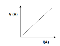
The gradient of a straight-line graph is constant and can be represented as follows:
[latex]\scriptsize \displaystyle \displaystyle \frac{{\Delta x}}{{\Delta y}}=\displaystyle \frac{{\Delta V}}{{\Delta I}}[/latex]
Ohm determined that the gradient of the graph represents the resistance ([latex]\scriptsize R[/latex]) of the resistor.
The formula for Ohm’s law is therefore: [latex]\scriptsize R=\displaystyle \frac{V}{I}[/latex]
Where:
[latex]\scriptsize I[/latex] is the current through the conductor (in amperes, A)
[latex]\scriptsize V[/latex] is the voltage across the conductor (in volts, V)
[latex]\scriptsize R[/latex] is the resistance of the conductor (in Ohms, [latex]\scriptsize \Omega[/latex]).
Activity 1.1: Determine the relationship between current going through a resistor and the potential difference (voltage) across the resistor (Ohm’s law)
Time required: 20 minutes
What you need:
- internet access
- graph paper
What to do:
- Copy the table below into your notebook.
Voltage ([latex]\scriptsize \text{V}[/latex]) Current ([latex]\scriptsize \text{mA}[/latex]) Current ([latex]\scriptsize \text{A x 1}{{\text{0}}^{{-3}}}[/latex] ) [latex]\scriptsize 0[/latex] [latex]\scriptsize 0[/latex] [latex]\scriptsize 0[/latex] [latex]\scriptsize 1[/latex] [latex]\scriptsize 2[/latex] [latex]\scriptsize 3[/latex] [latex]\scriptsize 4[/latex] [latex]\scriptsize 5[/latex] [latex]\scriptsize 6[/latex] [latex]\scriptsize 7[/latex] [latex]\scriptsize 8[/latex] [latex]\scriptsize 9[/latex] - Go to this simulation for Ohm’s law.
- Move the resistance slider to [latex]\scriptsize 365\text{ }\Omega[/latex]. Do not move this slider from here for the rest of the experiment.
- Carefully move the voltage slider to [latex]\scriptsize \text{1 V}[/latex].
- Record the current in milliAmps in the data table. Repeat, increasing the Voltage in increments of [latex]\scriptsize \text{1 V}[/latex] up to [latex]\scriptsize 9\text{ V}[/latex].
- Once data is recorded, close the simulation.
- The current needs to be in amperes ([latex]\scriptsize \text{A}[/latex]). Transfer your data directly into the third column of the table and note that the units will now be in [latex]\scriptsize \text{A x 1}{{\text{0}}^{{-3}}}[/latex]. These will be the units for the current in the label for the [latex]\scriptsize x[/latex]-axis of your graph.
- Plot your data on graph paper. Plot the current on the [latex]\scriptsize x[/latex]-axis and the voltage on the [latex]\scriptsize y[/latex]-axis.
- Draw a using a ruler.
- When you have plotted your graph. Calculate the of the graph using [latex]\scriptsize \displaystyle \frac{{\Delta y}}{{\Delta x}}=\displaystyle \frac{{{{y}_{2}}-{{y}_{1}}}}{{{{x}_{2}}-{{x}_{1}}}}[/latex].
- What do you notice about the shape of the graph? What does this indicate about the relationship between the voltage and the current?
- What do you notice about the value for the gradient of the graph (with a margin for experimental error)? (Refer to point 3 in these instructions).
What did you find?
- As the voltage in the circuit was increased, the current also increased.
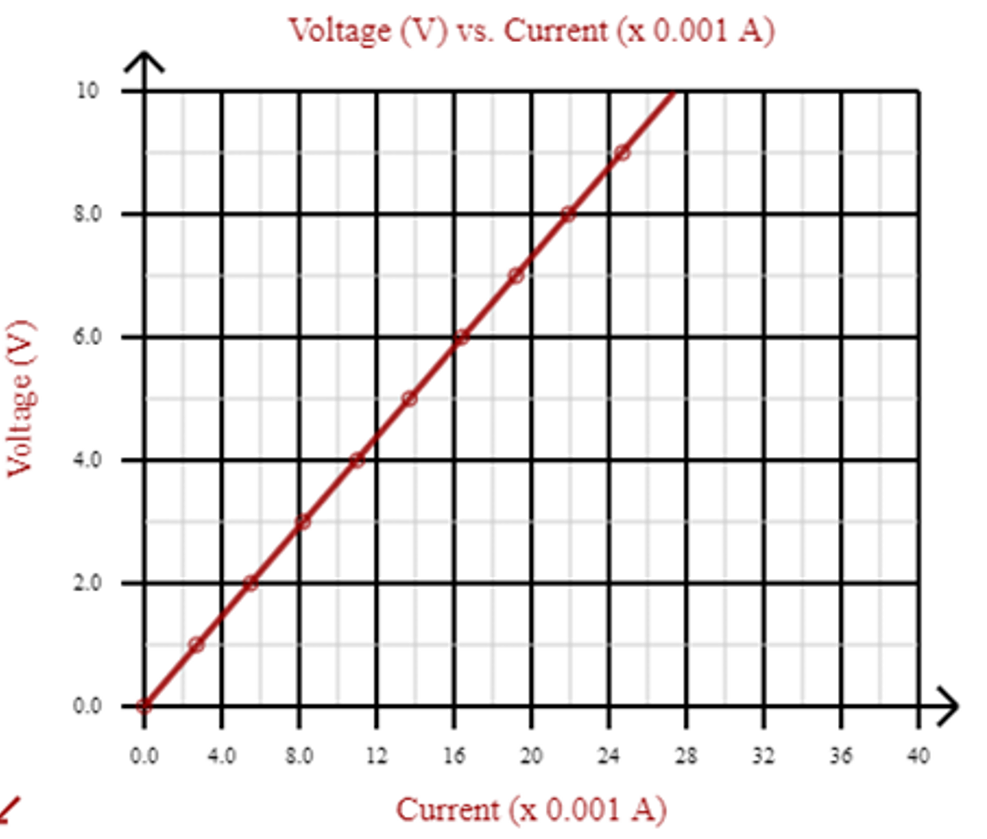
- The graph is a straight line through [latex]\scriptsize 0[/latex]. This means that the voltage is to the current.
- This confirms Ohm’s law which states that voltage across a conductor is directly proportional to the current through the conductor (when the temperature remains constant).
- The gradient of the graph is equivalent to the resistance of the resistor.
Applying Ohm’s law
We are now ready to see how Ohm’s law is used to analyse circuits.
Consider a circuit with a cell and a resistor, [latex]\scriptsize R[/latex]. If the resistor has a resistance of [latex]\scriptsize 5\text{ }\Omega[/latex] and voltage across the resistor is [latex]\scriptsize 5\text{ V}[/latex], then we can use Ohm’s law to calculate the current flowing through the resistor. The circuit diagram for this problem looks like this:

Figure 2: Circuit diagram with a resistor [latex]\scriptsize R[/latex] and one cell.
The equation for Ohm’s law is: [latex]\scriptsize R=\displaystyle \frac{V}{I}[/latex]
which can be rearranged to: [latex]\scriptsize I=\displaystyle \frac{V}{R}[/latex]
The current flowing through the resistor is: [latex]\scriptsize I=\displaystyle \frac{5}{5}=1\text{ A}[/latex]
Example 1.1
Study the circuit diagram below.

The resistance of the resistor is [latex]\scriptsize 10\text{ }\Omega[/latex] and the current going through the resistor is [latex]\scriptsize 4\text{ A}[/latex]. What is the potential difference (voltage) across the resistor?
Solution
Step 1: Write down the given information and what is being asked for
[latex]\scriptsize \begin{align*}R&=10\text{ }\Omega \\I&=4\text{ A}\\V&=\text{?}\end{align*}[/latex]
Step 2: Rearrange the equation above and substitute the known values for [latex]\scriptsize R[/latex] and [latex]\scriptsize I[/latex] to solve for [latex]\scriptsize V[/latex]
[latex]\scriptsize \begin{align*}V&=IR\\&=\text{4 x 10}\\&=\text{40 V}\end{align*}[/latex]
Step 3: Write the final answer
The voltage across the resistor is [latex]\scriptsize 40\text{ V}[/latex]
Summary
- Ohm’s law defines the relationship between the voltage across a conductor (resistor) and the current flowing through it.
- Ohm’s law is defined as: the amount of electric current through a metal conductor, at a constant temperature, in a circuit is directly proportional to the voltage across the conductor.
- The ratio of the voltage across a resistor to the current flowing through it is constant and is equivalent to the resistance of the resistor.
- The formula for Ohm’s law is: [latex]\scriptsize R=\displaystyle \frac{V}{I}[/latex].
- When the voltage across a resistor is plotted against the current flowing through it, the graph is a straight line through [latex]\scriptsize 0[/latex] which indicates a directly proportional relationship between these variables.
- The gradient of this straight-line graph is equivalent to the resistance of the resistor.
Unit 1: Assessment
Suggested time to complete: 15 minutes
- Give the formula for Ohm’s law and the units for the variables.
- Define Ohm’s law.
- Use the data in the table below to answer the following questions:
Voltage ([latex]\scriptsize \text{V}[/latex]) Current ([latex]\scriptsize \text{I}[/latex]) [latex]\scriptsize 0.0[/latex] [latex]\scriptsize 0.0[/latex] [latex]\scriptsize 0.4[/latex] [latex]\scriptsize 3.0[/latex] [latex]\scriptsize 0.8[/latex] [latex]\scriptsize 6.0[/latex] [latex]\scriptsize 1.2[/latex] [latex]\scriptsize 9.0[/latex] [latex]\scriptsize 1.6[/latex] [latex]\scriptsize 12.0[/latex] - Plot a graph of voltage (on the [latex]\scriptsize y[/latex]-axis) and current (on the [latex]\scriptsize x[/latex]-axis).
- What type of graph do you obtain? (straight line, parabola, other curve)
- Calculate the gradient of the graph.
- What does the gradient of the graph represent?
- What would the voltage be if the current reading was [latex]\scriptsize 7\text{ A}[/latex]? Indicate with dotted lines on your graph where you read off your answer.
- What would the current reading be if the voltage is [latex]\scriptsize 0.5\text{ V}[/latex]? Indicate with dotted lines on your graph where you read off your answer.
- Do your experimental results verify Ohm’s law? Explain.
- How would you go about finding the resistance of an unknown resistor experimentally?
- Calculate the resistance of a resistor that has a potential difference of [latex]\scriptsize 8\text{ V}[/latex] across it when a current of [latex]\scriptsize 2\text{ A}[/latex] flows through it.
- What current will flow through a resistor of [latex]\scriptsize 6\text{ }\Omega[/latex] when there is a potential difference of [latex]\scriptsize 18\text{ V}[/latex] across its ends?
- What is the voltage across a [latex]\scriptsize 10\text{ }\Omega[/latex] resistor when a current of [latex]\scriptsize 1.5\text{ A}[/latex] flows though it?
The full solutions are at the end of the unit.
Unit 1: Solutions
Unit 1: Assessment
- The formula for Ohm’s Law is: [latex]\scriptsize R=\displaystyle \frac{V}{I}[/latex]
Where:
[latex]\scriptsize I[/latex] is the current through the conductor (in amperes, A)
[latex]\scriptsize V[/latex] is the voltage across the conductor (in volts, V)
[latex]\scriptsize R[/latex] is the resistance of the conductor (in Ohms, [latex]\scriptsize \Omega[/latex]). - The amount of electric current through a metal conductor, at a constant temperature, in a circuit is directly proportional to the voltage across the conductor.
- .
- .
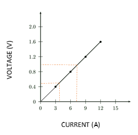
- straight line
- [latex]\scriptsize \displaystyle \frac{{\Delta y}}{{\Delta x}}=\displaystyle \frac{{1.2-0}}{{9-0}}=0.13[/latex]
- The resistance of the resistor is [latex]\scriptsize 0.13\text{ }\Omega[/latex].
- [latex]\scriptsize \pm 1\text{ V}[/latex]
- [latex]\scriptsize \pm 0.4\text{ V}[/latex]
- Yes – the graph is a straight line through [latex]\scriptsize 0[/latex], which indicates that the voltage is directly proportional to the current.
- .
- Place the unknown resistor into a circuit.
Connect a voltmeter in parallel across the resistor and an ammeter in series.
Take the voltage and current readings.
Use Ohm’s law, [latex]\scriptsize R=\displaystyle \frac{V}{I}[/latex], to calculate the resistance of the resistor. - [latex]\scriptsize R=\displaystyle \frac{V}{I}=\displaystyle \frac{8}{2}=4\text{ }\Omega[/latex]
- [latex]\scriptsize I=\displaystyle \frac{V}{R}=\displaystyle \frac{{18}}{6}=3\text{ A}[/latex]
- [latex]\scriptsize V=IR=1.5\text{ x 10 = 15 V}[/latex]
Media Attributions
- img01_Figure1 © DHET is licensed under a CC BY (Attribution) license
- img02_Activity1.1 © Siyavula is licensed under a CC BY-NC-ND (Attribution NonCommercial NoDerivatives) license
- img03_Figure2 © Siyavula is licensed under a CC BY-NC-ND (Attribution NonCommercial NoDerivatives) license
- img04_Example1.1 © Siyavula is licensed under a CC BY-NC-ND (Attribution NonCommercial NoDerivatives) license
- img05_AssessmentQ3answer © Siyavula is licensed under a CC BY-NC-ND (Attribution NonCommercial NoDerivatives) license
the amount of electric current through a metal conductor, at a constant temperature, in a circuit is directly proportional to the voltage across the conductor
a straight line drawn as close as possible to the plotted points
the slope of a straight-line graph, calculated using the formula
when one variable increases, the other variable increases by the same factor
