Mechanics: Describe, analyse and apply principles of concurrent forces
Unit 2: Components of a force
Linda Pretorius
Unit outcomes
By the end of this unit you will be able to:
- Determine components of a force by calculation or by construction.
- Identify an object or system of masses in equilibrium.
- Define, identify and calculate the equilibrant of a system.
What you should know
Before you start this unit, make sure you can:
- Explain why force is a vector. Refer to level 2 subject outcome 2.2 unit 1 if you need help with this.
- Define weight as a force. Refer to level 2 subject outcome 2.2 unit 3 if you need help with this.
- Define the resultant of a force. Refer to level 2 subject outcome 2.2 unit 1 if you need help with this.
- Define the equilibrant of vectors. Refer to level 2 subject outcome 2.1 unit 4 if you need help with this.
- Draw force diagrams. Refer to level 2 subject outcome 2.2 unit 2 if you need help with this.
- Draw vector diagrams of two forces acting simultaneously on a body. Refer to level 3 subject outcome 2.2 unit 1 if you need help with this.
- Determine the resultant of two forces acting simultaneously on a body. Refer to level 3 subject outcome 2.2 unit 1 if you need help with this.
Introduction
Parts of the text in this unit were sourced or adapted from Siyavula Physical Science Gr 11 Learner’s Book, p. 36–53, released under a CC-BY licence.
In this unit you will apply your knowledge about the resultant of a force to understand the components of a force. This, together with what you already know about the equilibrant of a system of vectors, will help you to understand how a combination of forces can work together to keep an object or system of masses balanced. We say such a system is in . Once you understand this concept you will be able to determine the equilibrant force of a system.
Finding the components of a force
From earlier units you already know that a number of vectors acting together, such as forces acting concurrently, can be combined to give a single vector. This is called the resultant. In much the same way a single vector can be broken down into a number of vectors that can be added up to give that original vector again. These vectors, which sum to the original, are called the of the original vector. The process of breaking a vector into its components is called resolving it into components.
Any vector can be resolved into a horizontal and a vertical component, which are at right angles to each other. This means that the x- and y-components are parallel to the x- and y-axes, respectively, in a Cartesian system. Resolving a vector into components that are at right angles to each other makes it easy to determine the size of these components. We usually indicate the components of a vector using the subscript x for the horizontal component and the subscript y for the vertical component. Therefore, when working with forces, the horizontal component for a force [latex]\scriptsize \overrightarrow{F}[/latex] would be given as [latex]\scriptsize \overrightarrow{{{{F}_{x}}}}[/latex] and its vertical component as [latex]\scriptsize \overrightarrow{{{{F}_{y}}}}[/latex].
Resolving a force into components by construction
When resolving a force into components that are parallel to the x- and y-axes, we are always dealing with a right-angled triangle. We can use this to construct vector diagrams to determine the magnitudes of the components. To resolve a force by construction, you will need a protractor and a ruler or set square.
Example 2.1
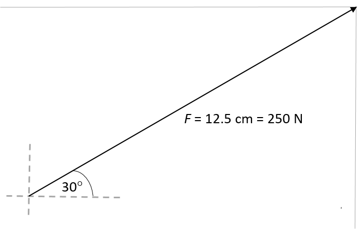
A force, [latex]\scriptsize \overrightarrow{F}[/latex], of [latex]\scriptsize 250\text{ N}[/latex] acts at an angle of [latex]\scriptsize 30^\circ[/latex] to the positive x-axis. Resolve this force into its x- and y-components by construction.
Solution
Define a suitable scale for the diagram, for example [latex]\scriptsize 1\text{ cm = 20 N}[/latex]. That means that the vector has to be drawn [latex]\scriptsize 12.5\text{ cm}[/latex] long.
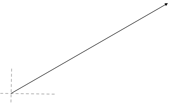
Draw sketch lines to indicate the positive x- and y-axes.
Use a protractor to measure an angle of [latex]\scriptsize 30^\circ[/latex] to the positive x-axis.
Use a ruler to draw in the force [latex]\scriptsize \overrightarrow{F}[/latex] at the correct length; in this case, [latex]\scriptsize 12.5\text{ cm}[/latex].
Draw a faint construction line running down from the head of force [latex]\scriptsize \overrightarrow{F}[/latex], parallel to the y-axis. Draw another construction line from the head of force [latex]\scriptsize \overrightarrow{F}[/latex] horizontally towards the y-axis, parallel to the x-axis.
Recall that in the tail-to-tail method of drawing vector diagrams, the resultant vector is represented as the diagonal of the parallelogram formed. That means that if we have the diagonal already – in this case [latex]\scriptsize \overrightarrow{F}[/latex] – the horizontal and vertical sides of the parallelogram are the x- and y-components of [latex]\scriptsize \overrightarrow{F}[/latex].
Draw an arrow from the tail of force [latex]\scriptsize \overrightarrow{F}[/latex] vertically up along the y-axis, to where it connects with the construction line. Measure the length accurately. In this case it is [latex]\scriptsize 6.2\text{ cm}[/latex].
Draw another arrow from the tail of force [latex]\scriptsize \overrightarrow{F}[/latex] horizontally along the x-axis, to where it connects with the construction line. Measure the length accurately. In this case it is [latex]\scriptsize \text{10}\text{.8 cm}[/latex].
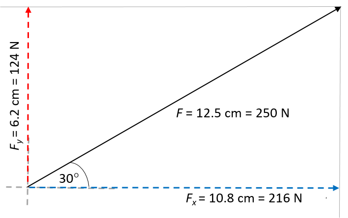
Using the defined scale, we find that [latex]\scriptsize {{F}_{y}}=6.2\times 20=124\text{ N}[/latex] and [latex]\scriptsize {{F}_{x}}=10.8\times 20=216\text{ N}[/latex]
Resolving a force into components by calculation
Because we are always dealing with a right-angled triangle when resolving a force into components that are parallel to the x- and y-axes, we can use trigonometric identities to determine the magnitudes of the components. (We know the directions because they are aligned with the axes.) Let’s look at the force [latex]\scriptsize \overrightarrow{F}[/latex] from example 2.1 again to calculate its components mathematically.
Example 2.2
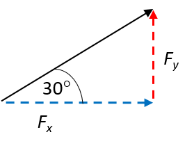
A force, [latex]\scriptsize \overrightarrow{F}[/latex], of [latex]\scriptsize 250\text{ N}[/latex] acts at an angle of [latex]\scriptsize 30^\circ[/latex] to the positive x-axis. Resolve this force into its x- and y-components by calculation.
Solution
Draw a rough sketch diagram to illustrate the given situation. Recall that the x- and y-components of a force create right-angled triangle when drawn as a head-to-tail vector diagram.
Use trigonometry to calculate the two components
For the x-component:
[latex]\scriptsize \displaystyle \begin{align*}\displaystyle \frac{{{{F}_{x}}}}{F}&=\cos 30^\circ \\\therefore {{F}_{x}}&=F\cos 30^\circ \\&=250\text{ N}\times 0.866\\&=216.5\text{ N}\end{align*}[/latex]
For the y-component:
[latex]\scriptsize \displaystyle \begin{align*}\displaystyle \frac{{{{F}_{y}}}}{F}&=\sin 30^\circ \\\therefore {{F}_{y}}&=F\sin 30^\circ \\&=250\text{ N}\times 0.5\\&=125\text{ N}\end{align*}[/latex]
We see that the values are close to what we determined by construction in example 2.1. The slight discrepancy can be attributed to a small margin of error when measuring the lines in the diagram.
Remember [latex]\scriptsize {{F}_{x}}[/latex] and [latex]\scriptsize {{F}_{y}}[/latex] are the magnitudes of the components. [latex]\scriptsize \overrightarrow{{{{F}_{x}}}}[/latex] is in the positive x-direction and [latex]\scriptsize \overrightarrow{{{{F}_{y}}}}[/latex] is in the positive y-direction.
Knowing how to resolve a vector into components also helps us to find the resultant of two or more concurrent forces of which neither is parallel to the x- or y-axes. Let’s look at an example.
Example 2.3
If [latex]\scriptsize \overrightarrow{{{{F}_{1}}}}=5.385\text{ N}[/latex] at an angle of [latex]\scriptsize 21.8^\circ[/latex] to the horizontal and [latex]\scriptsize \overrightarrow{{{{F}_{2}}}}=5\text{ N}[/latex] at an angle of [latex]\scriptsize 53.13^\circ[/latex] to the horizontal, find the resultant force, [latex]\scriptsize \overrightarrow{R}[/latex].
Solution
Both forces are at an angle to the x-axis so we can resolve each one into x- and y-components
The sum of the two x-components, [latex]\scriptsize {{F}_{{x1}}}[/latex] and [latex]\scriptsize {{F}_{{x2}}}[/latex], will be the same as the x-component of the resultant, namely [latex]\scriptsize {{R}_{x}}[/latex]. Similarly, the sum of the two y-components, [latex]\scriptsize \displaystyle {{F}_{{y1}}}[/latex]and [latex]\scriptsize {{F}_{{y2}}}[/latex], will be the same as the y-component of the resultant, namely [latex]\scriptsize {{R}_{y}}[/latex].
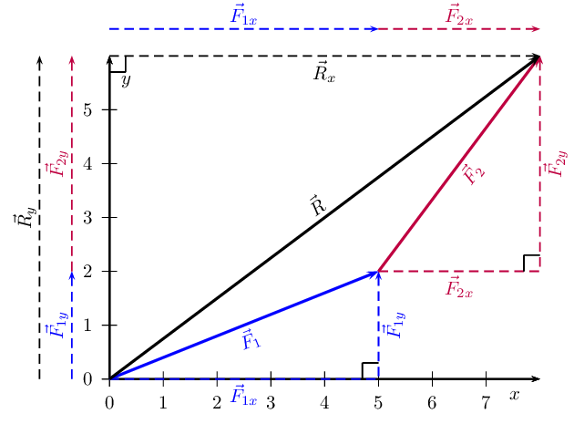
We find the components of the two forces by using known trigonometric ratios:
For the components of [latex]\scriptsize \overrightarrow{{{{F}_{1}}}}[/latex]:
| [latex]\scriptsize \displaystyle \begin{align*}\displaystyle \frac{{{{F}_{{x1}}}}}{{{{F}_{1}}}}&=\cos 21.8^\circ \\\therefore {{F}_{{x1}}}&={{F}_{1}}(\cos 21.8^\circ )\\&=5.385\text{ N}\times 0.928\\&=5.00\text{ N}\end{align*}[/latex] | [latex]\scriptsize \displaystyle \begin{align*}\displaystyle \frac{{{{F}_{{y1}}}}}{{{{F}_{1}}}}&=\sin 21.8^\circ \\\therefore {{F}_{{y1}}}&={{F}_{1}}(\sin 21.8^\circ )\\&=5.385\text{ N}\times 0.371\\&=2.00\text{ N}\end{align*}[/latex] |
For the components of [latex]\scriptsize \overrightarrow{{{{F}_{2}}}}[/latex]:
| [latex]\scriptsize \displaystyle \begin{align*}\displaystyle \frac{{{{F}_{{x2}}}}}{{{{F}_{2}}}}&=\cos 53.13^\circ \\\therefore {{F}_{{x2}}}&={{F}_{2}}(\cos 53.13^\circ )\\&=5\text{ N}\times 0.6\\&=3.00\text{ N}\end{align*}[/latex] | [latex]\scriptsize \displaystyle \begin{align*}\displaystyle \frac{{{{F}_{{y2}}}}}{{{{F}_{2}}}}&=\sin 53.13^\circ \\\therefore {{F}_{{y2}}}&={{F}_{2}}(\sin 53.13^\circ )\\&=5\text{ N}\times 0.8\\&=4.\text{00}\ \text{N}\end{align*}[/latex] |
Now add the x-components and the y-components. It is useful to draw up a table to do this. Also remember that vectors are additive, so the order in which they are added does not matter.
| Vector | x-component | y-component |
| [latex]\scriptsize \overrightarrow{{{{F}_{1}}}}[/latex] | [latex]\scriptsize 5.00\text{ N}[/latex] | [latex]\scriptsize 2.00\text{ N}[/latex] |
| [latex]\scriptsize \overrightarrow{{{{F}_{2}}}}[/latex] | [latex]\scriptsize 3.00\text{ N}[/latex] | [latex]\scriptsize \text{4}\text{.00 N}[/latex] |
| [latex]\scriptsize \overrightarrow{R}[/latex] | [latex]\scriptsize 8.00\text{ N}[/latex] | [latex]\scriptsize 6.00\text{ N}[/latex] |
Note
Remember that we must define which directions are positive, for example to the right as the positive horizontal direction and upwards as the positive vertical direction.
Now that we have the components of the resultant, we can use the Pythagoras’ theorem to determine the magnitude of the resultant force, [latex]\scriptsize \displaystyle \overrightarrow{R}[/latex].
[latex]\scriptsize \displaystyle \begin{align*}{{R}^{2}}&={{({{R}_{x}})}^{2}}+{{({{R}_{y}})}^{2}}\\&={{(8.00)}^{2}}+{{(6.00)}^{2}}\\&=100.00\\\therefore R&=\sqrt{{100.00}}\\&=10.00\text{ N}\end{align*}[/latex]
The magnitude of the resultant, [latex]\scriptsize \overrightarrow{R}[/latex], is [latex]\scriptsize 10.00\text{ N}[/latex]. So all we must do is calculate its direction. We can specify the direction as the angle the vectors makes with a known direction. To do this you only need to visualise the vector as starting at the origin of a coordinate system. We have drawn this explicitly below and the angle we will calculate is labelled [latex]\scriptsize \alpha[/latex].
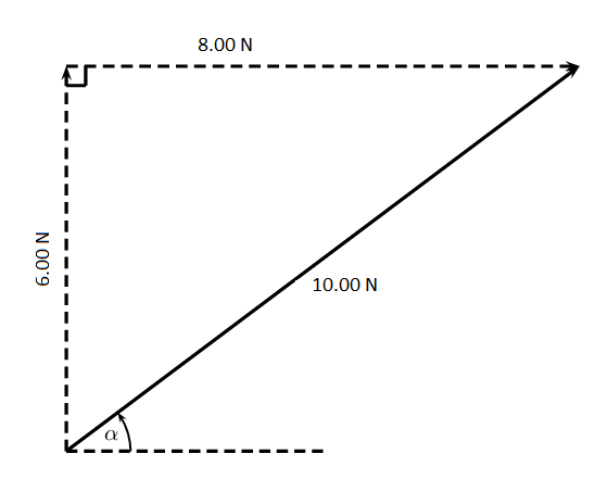
Using known trigonometric ratios we can calculate the value of [latex]\scriptsize \alpha[/latex]:
[latex]\scriptsize \begin{align*}\tan \alpha &=\displaystyle \frac{{6.00}}{{8.00}}\\\alpha &={{\tan }^{{-1}}}(\displaystyle \frac{{6.00}}{{8.00}})\\\alpha &=36.9^\circ \end{align*}[/latex]
Therefore the resultant force, [latex]\scriptsize \overrightarrow{R}[/latex], is [latex]\scriptsize 10.00\text{ N}[/latex] at an angle of [latex]\scriptsize 36.9^\circ[/latex] to the positive x-axis.
Note
To revise resolving a force into components, watch this video.
Exercise 2.1
- Resolve the following forces into components by calculation:
- [latex]\scriptsize \displaystyle \overrightarrow{F}=15\text{ N}[/latex] at [latex]\scriptsize 63^\circ[/latex] to the positive x-axis.
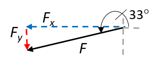
- [latex]\scriptsize \displaystyle \overrightarrow{F}=11\times {{10}^{4}}\text{ N}[/latex] at [latex]\scriptsize 33^\circ[/latex] to the positive x-axis.
- [latex]\scriptsize \displaystyle \overrightarrow{F}=11.3\text{ kN}[/latex] at [latex]\scriptsize 193^\circ[/latex] to the positive x-axis.
- Find the components of the following forces by construction:
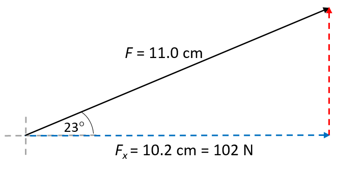
- [latex]\scriptsize \displaystyle \overrightarrow{{{{F}_{1}}}}=110\text{ N}[/latex] at [latex]\scriptsize 23^\circ[/latex] to the positive x-axis.
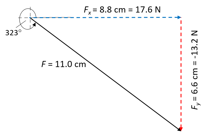
- [latex]\scriptsize \displaystyle \overrightarrow{{{{F}_{2}}}}=22\text{ N}[/latex] at [latex]\scriptsize 323^\circ[/latex] to the positive x-axis.
The full solutions can be found at the end of the unit.
Objects in equilibrium
When all forces acting on an object are balanced, we say the object is in equilibrium. This means there is no net force acting on the object. In other words, the vector sum of all the forces is zero: [latex]\scriptsize \sum F=0[/latex]. Recall that the vector sum of the forces in a system is called the resultant. Therefore we can also say that if a system is in equilibrium, its resultant is zero.
An object in equilibrium has the following characteristics:
- all the individual forces acting on the object are balanced
- the resultant is zero: [latex]\scriptsize \displaystyle \sum F=0[/latex]
- the object experiences no acceleration. That means it is at rest or moving at constant velocity.
We can explore a system of masses that are in equilibrium practically using a force board.
Activity 2.1: Explore a system of masses in equilibrium
Time required: 20 minutes
What you need:
- a phone with a QR scanner (optional)
- an internet connection
- a scientific calculator
- a large sheet of paper
- a pencil, ruler and protractor
What to do:
- Watch the video ‘Forces in equilibrium’ (Duration: 11.05)
- Use what you have learnt in the video to answer the following questions:
- What would happen if we changed the mass pieces in the practical in the video so that the magnitudes of the forces are now as follows:
- [latex]\scriptsize \displaystyle {{F}_{1}}=3\text{ N}[/latex]
- [latex]\scriptsize \displaystyle {{F}_{2}}=2\text{ N}[/latex]
- [latex]\scriptsize \displaystyle {{F}_{3}}=8\text{ N}[/latex]
- What would happen if we changed the mass pieces in the practical in the video so that the magnitudes of the forces are now as follows:
- [latex]\scriptsize \displaystyle {{F}_{1}}=5\text{ N}[/latex]
- [latex]\scriptsize \displaystyle {{F}_{2}}=2\text{ N}[/latex]
- [latex]\scriptsize \displaystyle {{F}_{3}}=4\text{ N}[/latex]
- What would happen if we changed the mass pieces in the practical in the video so that the magnitudes of the forces are now as follows:
- What can you conclude from your observations?
What did you find?
- The practical in the video shows a system of masses in equilibrium. That means all the downward forces are balanced by the various upward forces.
- Increasing F3 will increase the angle between the horizontal and both F1 and F2. That is because the y-component of both F1 and F2 needs to increase to balance the larger downward force in the system caused by F3.
- Similarly, increasing F1 will cause the y-components of the other two forces to change to balance the large downward force of F1 in the system.
- The practical shows how components of the individual forces change to keep the system in equilibrium. Drawing vector diagrams will give closed polygons every time, which tells us that the system settles into a new equilibrium after each change to the mass pieces (forces).
Equilibrant of a system
In level 2 subject outcome 2.1 unit 4, you learnt that the is the force equal in magnitude to the resultant, but opposite in direction. In the context of a system of forces, the equilibrant is therefore the force that will cause the sum of the others to be zero. In activity 2.1, the system was in equilibrium. The resultant was zero, as was shown by the vector diagram forming a closed triangle when the vectors were drawn head to tail.
Understanding the concept of forces in equilibrium is useful in practical applications, as it helps us to determine the conditions required to keep a system in equilibrium. You will practise this in more examples in the next unit.
In a system of forces, the equilibrant is the force that will cause the sum of the other forces to be zero. It is equal in magnitude to the resultant but opposite in direction.
Example 2.4
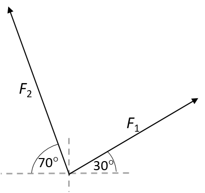
Consider two concurrent forces acting on an object, as shown in the diagram:
- [latex]\scriptsize \displaystyle {{F}_{1}}=10.00\text{ N}[/latex] at [latex]\scriptsize 30^\circ[/latex] to the positive x-axis
- [latex]\scriptsize \displaystyle {{F}_{2}}=12.00\text{ N}[/latex] at [latex]\scriptsize 70^\circ[/latex] to the negative x-axis
What force would be required to keep the system in equilibrium?
 |
Take the positive x-direction as to the right and the positive y-direction as upwards. |
Solution
The question asks us to determine the equilibrant of the system. If we draw a tail-to-head vector diagram, it will be the vector that creates a closed triangle. It is shown as [latex]\scriptsize {{F}_{3}}[/latex] in the diagram.
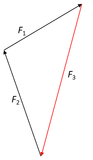
We can then use simple trigonometric ratios to determine the magnitude of the equilibrant. Because the equilibrant is the force that will make the sum of the other forces zero, it follows that the magnitude of its y-component must be equal to the sum of the y-components of the other forces. The same principle applies to determining the x-component of the equilibrant.
For F1:
| [latex]\scriptsize \displaystyle \begin{align*}\displaystyle \frac{{{{F}_{{x1}}}}}{{{{F}_{1}}}}&=\cos 30^\circ \\\therefore {{F}_{{x1}}}&={{F}_{1}}(\cos 30^\circ )\\&=10.00\text{ N}\times 0.866\\&=8.66\text{ N}\end{align*}[/latex] | [latex]\scriptsize \displaystyle \begin{align*}\displaystyle \frac{{{{F}_{{y1}}}}}{{{{F}_{1}}}}&=\sin 30^\circ \\\therefore {{F}_{{y1}}}&={{F}_{1}}(\sin 30^\circ )\\&=10.00\text{ N}\times 0.5\\&=5.00\text{ N}\end{align*}[/latex] |
F2 is at an angle of [latex]\scriptsize 70^\circ[/latex] to the negative x-axis. That means it is at [latex]\scriptsize \displaystyle 180^\circ -70^\circ =110^\circ[/latex] to the positive x-axis. Therefore, for F2:
| [latex]\scriptsize \displaystyle \begin{align*}\displaystyle \frac{{{{F}_{{x2}}}}}{{{{F}_{2}}}}&=\cos 110^\circ \\\therefore {{F}_{{x2}}}&={{F}_{2}}(\cos 110^\circ )\\&=(12.00\text{ N)}\times (-0.342)\\&=-4.10\text{ N}\end{align*}[/latex] | [latex]\scriptsize \displaystyle \begin{align*}\displaystyle \frac{{{{F}_{{y2}}}}}{{{{F}_{2}}}}&=\sin 110^\circ \\\therefore {{F}_{{y2}}}&={{F}_{2}}(\sin 110^\circ )\\&=(12.00\text{ N)}\times 0.939\\&=11.28\text{ N}\end{align*}[/latex] |
Now add all the x-components together, as well as all the y-components.
| Vector | x-component | y-component |
| F1 | [latex]\scriptsize 8.66\text{ N}[/latex] | [latex]\scriptsize 5.00\text{ N}[/latex] |
| F2 | [latex]\scriptsize -4.10\text{ N}[/latex] | [latex]\scriptsize \text{11}\text{.28 N}[/latex] |
| [latex]\scriptsize \sum F[/latex] | [latex]\scriptsize 4.56\text{ N}[/latex] | [latex]\scriptsize 16.28\text{ N}[/latex] |
The sum of the forces, [latex]\scriptsize \sum F[/latex], is the resultant. Because the equilibrant has the same magnitude as the resultant but opposite direction, it follows that the x-component of [latex]\scriptsize {{F}_{{x3}}}[/latex] is [latex]\scriptsize 4.56\text{ N}[/latex] in the negative x-direction, i.e. [latex]\scriptsize {{F}_{{x3}}}=-4.56\text{ N}[/latex], and its y-component [latex]\scriptsize \displaystyle {{F}_{{y3}}}[/latex] is [latex]\scriptsize \displaystyle 16.28\text{ N}[/latex] in the negative y-direction, i.e. [latex]\scriptsize \displaystyle {{F}_{{y3}}}=-16.28\text{ N}[/latex].
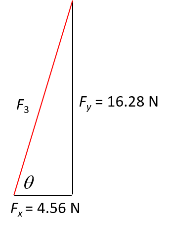 |
We can now use the x- and y-components to draw a right-angled triangle. The equilibrant, [latex]\scriptsize {{F}_{3}}[/latex], is represented by the hypotenuse of the triangle at an angle of [latex]\scriptsize \theta[/latex]. |
To find the magnitude of the equilibrant, we use the Pythagoras’ theorem:
[latex]\scriptsize \displaystyle \begin{align*}{{F}_{3}}^{2}&={{({{F}_{{x3}}})}^{2}}+{{({{F}_{{y3}}})}^{2}}\\&={{(4.56)}^{2}}+{{(16.28)}^{2}}\\&=285.83\\\therefore {{F}_{3}}&=\sqrt{{285.83}}\\&=16.91\text{ N}\end{align*}[/latex]
To find the angle, we use a simple trigonometric ratio:
[latex]\scriptsize \begin{align*}\tan \theta &=\displaystyle \frac{{16.28}}{{4.56}}\\\theta &={{\tan }^{{-1}}}(\displaystyle \frac{{16.28}}{{4.56}})\\\theta &=74.35^\circ \end{align*}[/latex]
Therefore, [latex]\scriptsize {{F}_{3}}=16.91\text{ N}[/latex] at [latex]\scriptsize 74.35^\circ[/latex] from the horizontal.
Exercise 2.2
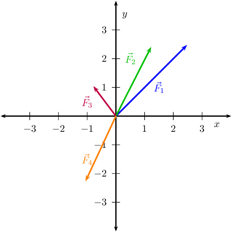
- [1] Determine, by resolving into components, the equilibrant of the following four forces acting at a point:
- [latex]\scriptsize \overrightarrow{{{{F}_{1}}}}=3.5\text{ N}[/latex] at [latex]\scriptsize 45^\circ[/latex] to the positive x-axis
- [latex]\scriptsize \overrightarrow{{{{F}_{2}}}}=2.7\text{ N}[/latex] at [latex]\scriptsize 63^\circ[/latex] to the positive x-axis
- [latex]\scriptsize \overrightarrow{{{{F}_{3}}}}=1.3\text{ N}[/latex] at [latex]\scriptsize 127^\circ[/latex] to the positive x-axis
- [latex]\scriptsize \overrightarrow{{{{F}_{4}}}}=2.5\text{ N}[/latex] at [latex]\scriptsize 245^\circ[/latex] to the positive x-axis
- Choose the statement or statements that are true:
A point is acted on by two forces and the resultant is zero. The forces:- have equal magnitudes and directions.
- have equal magnitudes but opposite directions.
- act perpendicular to each other.
- act in the same direction.
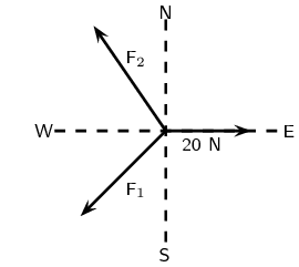
- A point is acted on by three forces in equilibrium, as indicated in the diagram below. Force [latex]\scriptsize {{F}_{1}}[/latex] has components [latex]\scriptsize \text{15 N}[/latex] due south and [latex]\scriptsize \text{13 N}[/latex] due west. What are the components of force [latex]\scriptsize {{F}_{2}}[/latex]?
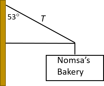
- A sign of [latex]\scriptsize 2.3\text{ kg}[/latex] attached to a horizontal beam hangs outside a shop. The beam is attached to the wall by a taut cable. Determine the tension (i.e. the pulling force) in the cable.
The full solutions can be found at the end of the unit.
Summary
In this unit you have learnt the following:
- The components of a vector are a series of vectors that, when combined, give the original vector as their resultant.
- Components are usually created that align with the Cartesian coordinate axes.
- Vectors can be added algebraically using Pythagoras’ theorem or by resolving them into components.
- The direction of a vector can be found using simple trigonometric calculations.
- For a vector [latex]\scriptsize \overrightarrow{F}[/latex] that makes an angle of [latex]\scriptsize \theta[/latex] with the positive x-axis, the x-component is [latex]\scriptsize \displaystyle {{\overrightarrow{R}}_{x}}=R\cos \theta[/latex] and the y-component is [latex]\scriptsize \displaystyle {{\overrightarrow{R}}_{y}}=R\sin \theta[/latex].
- If [latex]\scriptsize \sum F=0[/latex] in a system, the system is in equilibrium. That means all the forces are balanced.
- A closed vector diagram is a set of vectors drawn on the Cartesian coordinate system using the tail-to-head method and that has a resultant with a magnitude of zero.
- The equilibrant is the force that keeps the system in equilibrium. It has the same magnitude as the resultant but is opposite in direction.
- When an object or system of masses is in equilibrium it experiences no acceleration. That means it is at rest or moving at constant velocity.
- A closed vector diagram can be drawn for a system that is in equilibrium.
Unit 2: Assessment
Questions 1 and 2 are taken from Exercise 2.10 in the Siyavula Gr 11 Physical Science Learner’s Book on pp. 120–131, released under a CC-BY licence.
Suggested time to complete: 25 minutes
- P and Q are two forces of equal magnitude applied simultaneously to a body at X.

.
As the angle [latex]\scriptsize \theta[/latex] between the forces is decreased from [latex]\scriptsize 180^\circ[/latex] to [latex]\scriptsize 0^\circ[/latex], the magnitude of the resultant of the two forces will:- initially increase and then decrease.
- initially decrease and then increase.
- increase only.
- decrease only.
Give a reason for your answer with reference to the components of the resultant.
- As a result of three forces [latex]\scriptsize {{F}_{1}}[/latex], [latex]\scriptsize {{F}_{2}}[/latex] and [latex]\scriptsize {{F}_{3}}[/latex] acting on it, an object at point P is in equilibrium.
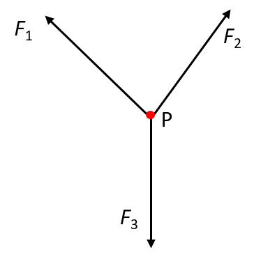
.
Which of the following statements is not true with reference to the three forces?- The resultant of forces [latex]\scriptsize {{F}_{1}}[/latex], [latex]\scriptsize {{F}_{2}}[/latex] and [latex]\scriptsize {{F}_{3}}[/latex] is zero.
- Force [latex]\scriptsize {{F}_{1}}[/latex], [latex]\scriptsize {{F}_{2}}[/latex] and [latex]\scriptsize {{F}_{3}}[/latex] lie in the same plane.
- Force [latex]\scriptsize {{F}_{3}}[/latex] is the resultant of forces [latex]\scriptsize {{F}_{1}}[/latex] and [latex]\scriptsize {{F}_{2}}[/latex].
- The sum of the components of all the forces in any chosen direction is zero.
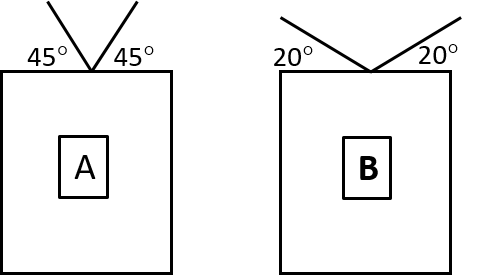
- Picture frames A and B are both hanging perfectly straight. Which object is heavier? Give a reason for your answer. Assume that the tensions in the two strings are the same in each case.
- A sign hangs on a wall, but it is not straight. What should you do to get the system into equilibrium, and why?

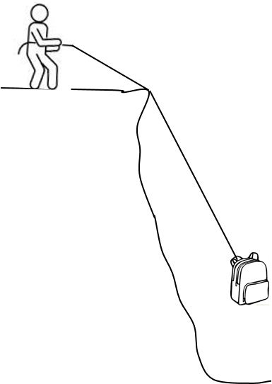
- A hiker’s backpack (mass = [latex]\scriptsize 30\text{ kg}[/latex]) fell down a cliff with a slope of [latex]\scriptsize 75^\circ[/latex]. The hiker clambers down along a few ledges and then ties a rope to the backpack so that his friend standing at the top of the cliff can hoist the backpack up. Determine the tension in the rope when the backpack hangs at rest in the air for a short while.
The full solutions can be found at the end of the unit.
Unit 2: Solutions
Exercise 2.1
- .
- Draw a rough sketch to help you visualise the problem.
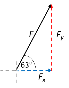
[latex]\scriptsize \displaystyle \begin{align*}\displaystyle \frac{{{{F}_{x}}}}{F}&=\cos 63^\circ \\\therefore {{F}_{x}}&=F\cos 63^\circ \\&=15\text{ N}\times 0.454\\&=6.81\text{ N}\end{align*}[/latex] [latex]\scriptsize \displaystyle \begin{align*}\displaystyle \frac{{{{F}_{y}}}}{F}&=\sin 63^\circ \\\therefore {{F}_{y}}&=F\sin 63^\circ \\&=15\text{ N}\times 891\\&=13.37\text{ N}\end{align*}[/latex] - Draw a rough sketch to help you visualise the problem.
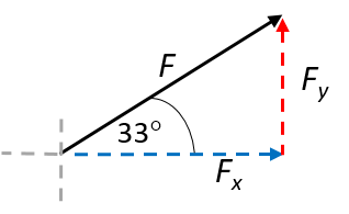
[latex]\scriptsize \displaystyle \begin{align*}\displaystyle \frac{{{{F}_{x}}}}{F}&=\cos 33^\circ \\\therefore {{F}_{x}}&=F\cos 33^\circ \\&=(11\times {{10}^{4}}\text{)}\times (0.839)\\&=92.25\times {{10}^{3}}\text{ N}\end{align*}[/latex] [latex]\scriptsize \displaystyle \begin{align*}\displaystyle \frac{{{{F}_{y}}}}{F}&=\sin 33^\circ \\\therefore {{F}_{y}}&=F\sin 33^\circ \\&=(11\times {{10}^{4}}\text{)}\times (0.545)\\&=59.91\times {{10}^{3}}\text{ N}\end{align*}[/latex] - Draw a rough sketch to help you visualise the problem.
[latex]\scriptsize \displaystyle \begin{align*}\displaystyle \frac{{{{F}_{x}}}}{F}&=\cos 193^\circ \\\therefore {{F}_{x}}&=F\cos 193^\circ \\&=(11.3\times {{10}^{3}}\text{)}\times (-0.974)\\&=-11.01\times {{10}^{3}}\text{ N}\end{align*}[/latex] [latex]\scriptsize \displaystyle \begin{align*}\displaystyle \frac{{{{F}_{y}}}}{F}&=\sin 193^\circ \\\therefore {{F}_{y}}&=F\sin 193^\circ \\&=(11.3\times {{10}^{3}}\text{)}\times (-0.225)\\&=-2.54\times {{10}^{3}}\text{ N}\end{align*}[/latex]
- Draw a rough sketch to help you visualise the problem.
- .
- Scale: [latex]\scriptsize 1\text{ cm = 10 }\text{N}[/latex]
[latex]\scriptsize {{F}_{x}}=102\text{ }\text{N}[/latex]
[latex]\scriptsize {{F}_{y}}=43\text{ }\text{N}[/latex]
- Scale: [latex]\scriptsize 1\text{ cm = 2 }\text{N}[/latex]
[latex]\scriptsize {{F}_{x}}=17.6\text{ }\text{N}[/latex]
[latex]\scriptsize {{F}_{y}}=13.2\text{ }\text{N}[/latex]
- Scale: [latex]\scriptsize 1\text{ cm = 10 }\text{N}[/latex]
Exercise 2.2
- Draw a sketch to help visualise the problem.
We are asked to determine the equilibrant, which we know is the opposite of the resultant. We therefore determine the resultant first by summing all the x-components of the individual forces and all the y-components. Vector x-component y-component F1 [latex]\scriptsize \begin{align*}{{F}_{{x1}}}&={{F}_{1}}\cos 45^\circ \\&=(3.5)(0.707)\\&=2.47\text{ N}\end{align*}[/latex] [latex]\scriptsize \begin{align*}{{F}_{{y1}}}&={{F}_{1}}\sin 45^\circ \\&=(3.5)(0.707)\\&=2.47\text{ N}\end{align*}[/latex] F2 [latex]\scriptsize \begin{align*}{{F}_{{x2}}}&={{F}_{2}}\cos 63^\circ \\&=(2.7)(0.454)\\&=1.23\text{ N}\end{align*}[/latex] [latex]\scriptsize \begin{align*}{{F}_{{y2}}}&={{F}_{2}}\sin 63^\circ \\&=(2.7)(0.891)\\&=2.41\text{ N}\end{align*}[/latex] F3 [latex]\scriptsize \begin{align*}{{F}_{{x3}}}&={{F}_{3}}\cos 127^\circ \\&=(1.3)(-0.602)\\&=-0.78\text{ N}\end{align*}[/latex] [latex]\scriptsize \begin{align*}{{F}_{{y3}}}&={{F}_{y}}\sin 127^\circ \\&=(1.3)(0.799)\\&=1.04\text{ N}\end{align*}[/latex] F4 [latex]\scriptsize \begin{align*}{{F}_{{x4}}}&={{F}_{4}}\cos 245^\circ \\&=(2.5)(0.423)\\&=-1.06\text{ N}\end{align*}[/latex] [latex]\scriptsize \begin{align*}{{F}_{{y4}}}&={{F}_{4}}\sin 245^\circ \\&=(2.5)(-0.906)\\&=-2.27\text{ N}\end{align*}[/latex] R [latex]\scriptsize {{R}_{x}}=1.86\text{ N}[/latex] [latex]\scriptsize {{R}_{y}}=3.65\text{ N}[/latex]
Note
For a quick check as you work, remember which ratios are positive in each quadrant of the Cartesian system using the CAST rule.

We can draw a rough sketch of the resultant because we have its x- and y-components.

| [latex]\scriptsize \displaystyle \begin{align*}{{R}^{2}}&={{({{R}_{x}})}^{2}}+{{({{R}_{y}})}^{2}}\\&={{(1.86)}^{2}}+{{(3.65)}^{2}}\\&=16.782\\\therefore R&=\sqrt{{16.782}}\\&=4.10\text{ N}\end{align*}[/latex] | [latex]\scriptsize \displaystyle \begin{align*}\tan \theta &=\displaystyle \frac{{{{R}_{y}}}}{{{{R}_{x}}}}\\\tan \theta &=\displaystyle \frac{{3.65}}{{1.86}}\\\theta &={{\tan }^{{-1}}}(\displaystyle \frac{{3.65}}{{1.86}})\\\theta &=63^\circ \end{align*}[/latex] |
Therefore: [latex]\scriptsize R=4.10\text{ N}[/latex] at angle of [latex]\scriptsize 63^\circ[/latex] to the positive x-axis.
The equilibrant is therefore [latex]\scriptsize 4.1\text{ N}[/latex] at [latex]\scriptsize 180^\circ +63^\circ =243^\circ[/latex].
- B. have equal magnitudes but opposite directions.
- Define east as the positive x-direction and north as the positive y-direction.
The object is in equilibrium, so [latex]\scriptsize \sum {{F}_{y}}=0[/latex] and [latex]\scriptsize \sum {{F}_{x}}=0[/latex].
We know that [latex]\scriptsize {{F}_{{y1}}}=15\text{ N}[/latex] due south, so [latex]\scriptsize \displaystyle {{F}_{{y2}}}=15\text{ N}[/latex] acting due north.
[latex]\scriptsize \begin{align*}\sum {{F}_{x}}&={{F}_{{x1}}}+{{F}_{{x2}}}+20\text{ N}\\\therefore {{F}_{{x2}}}&=-20+13\\&=-7\text{ N}\end{align*}[/latex]
Therefore: [latex]\scriptsize \displaystyle {{F}_{{x2}}}=7\text{ N}[/latex] due west and [latex]\scriptsize \displaystyle {{F}_{{y2}}}=15\text{ N}[/latex] due north. - Draw a force diagram to visualise the problem.
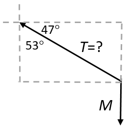
[latex]\scriptsize \begin{align*}W&=mg={{T}_{y}}\\{{T}_{y}}&=(2.3)(9.8)\\&=22.54\text{ N}\\T&=\displaystyle \frac{{{{T}_{y}}}}{{\sin 47^\circ }}\\&=\displaystyle \frac{{22.54}}{{0.731}}\\&=30.83\ \text{N}\end{align*}[/latex]
Unit 2: Assessment
- C. Increase only. This is because the y-component of the resultant will increase as the angle of the resultant changes from [latex]\scriptsize 180^\circ[/latex] towards [latex]\scriptsize 90^\circ[/latex], and the x-component of the resultant will increase as the angle changes from [latex]\scriptsize 90^\circ[/latex] towards [latex]\scriptsize 0^\circ[/latex].
- C. Force [latex]\scriptsize {{F}_{3}}[/latex] is the equilibrant of forces [latex]\scriptsize {{F}_{1}}[/latex] and [latex]\scriptsize {{F}_{2}}[/latex], not the resultant.
- The tension forces in A have bigger y-components than those in B. This means that the upward forces in A can balance a larger downward force (weight) than in B. Picture frame A is therefore the heavier of the two.
- String A should be shortened, which would lengthen string B at the same time. Because the angles with the horizontal will then be the same, the y-components of each string will be equal. They will each contribute one half of the upward force, which together will balance the downward force (weight) of the sign.
- Draw a force diagram to visualise the problem.
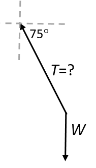
[latex]\scriptsize \displaystyle \begin{align*}\displaystyle \frac{{{{T}_{y}}}}{T}&=\sin 75^\circ \\\therefore T&=\displaystyle \frac{{{{T}_{y}}}}{{\sin 75^\circ }}\\&=\displaystyle \frac{{(30)(9.8)}}{{0.966}}\\&=304.35\text{ N}\end{align*}[/latex]
Media Attributions
- PS 3_2.2_2_Img01a © DHET is licensed under a CC BY (Attribution) license
- PS 3_2.2_2_Img01b © DHET is licensed under a CC BY (Attribution) license
- PS 3_2.2_2_Img01c © DHET is licensed under a CC BY (Attribution) license
- PS 3_2.2_2_Img02 © DHET is licensed under a CC BY (Attribution) license
- PS 3_2.2_2_Img03 © Siyavula is licensed under a CC BY (Attribution) license
- PS 3_2.2_2_Img04 © Siyavula is licensed under a CC BY (Attribution) license
- PS 3_2.2_2_Img05 © DHET is licensed under a CC BY (Attribution) license
- PS 3_2.2_2_Img06 © DHET is licensed under a CC BY (Attribution) license
- PS 3_2.2_2_Img07 © DHET is licensed under a CC BY (Attribution) license
- PS 3_2.2_2_Img08 © Siyavula is licensed under a CC BY (Attribution) license
- PS 3_2.2_2_Img09 © DHET is licensed under a CC BY (Attribution) license
- PS 3_2.2_2_Img010 © DHET is licensed under a CC BY (Attribution) license
- PS 3_2.2_2_Img011 © DHET is licensed under a CC BY (Attribution) license
- PS 3_2.2_2_Img012 © DHET is licensed under a CC BY (Attribution) license
- PS 3_2.2_2_Img013 © Rainy Wong is licensed under a CC0 (Creative Commons Zero) license
- PS 3_2.2_2_Img014 © DHET is licensed under a CC BY (Attribution) license
- PS 3_2.2_2_Img015 © DHET is licensed under a CC BY (Attribution) license
- PS 3_2.2_2_Img016 © DHET is licensed under a CC BY (Attribution) license
- PS 3_2.2_2_Img017 adapted by DHET is licensed under a CC BY (Attribution) license
- PS 3_2.2_2_Img018 © DHET is licensed under a CC BY (Attribution) license
- PS 3_2.2_2_Img019 © DHET is licensed under a CC BY (Attribution) license
- PS 3_2.2_2_Img020 © Siyavula is licensed under a CC BY (Attribution) license
- PS 3_2.2_2_Img021 © DHET is licensed under a CC BY (Attribution) license
- PS 3_2.2_2_Img022 © DHET is licensed under a CC BY (Attribution) license
- PS 3_2.2_2_Img023 © DHET is licensed under a CC BY (Attribution) license
- PS 3_2.2_2_Img024 © DHET is licensed under a CC BY (Attribution) license
- Questions 1–3 are taken from Exercise 1-7 in the Siyavula Gr 11 Physical Science Learner’s Book on pp. 50–53, released under a CC-BY licence. ↵
a state in which all forces in a system are balanced
the vertical and horizontal contributions to a force that acts at an angle to the x- or y-axes of a Cartesian system
the force that keeps a system in equilibrium
