Mechanics: Describe, analyse and apply principles of concurrent forces
Unit 3: Determine the unknown force in a system
Linda Pretorius
Unit outcomes
By the end of this unit you will be able to:
- Draw a labelled force diagram (free-body diagram) and vector diagram of three non-parallel forces in equilibrium and find unknown force by construction or mathematically as applied to:
- mass in suspension on ropes or cables
- mass on an inclined plane
- object with frictional force acting on it.
What you should know
Before you start this unit, make sure you can:
- Draw force diagrams. Refer to level 2 subject outcome 2.2 unit 2 if you need help with this.
- Draw vector diagrams of forces acting concurrently. Refer to level 3 subject outcome 2.2 unit 1 if you need help with this.
- Determine the resultant or equilibrant of a system. Refer to level 3 subject outcome 2.2 unit 2 if you need help with this.
- Resolve a force into components. Refer to level 3 subject outcome 2.2 unit 2 if you need help with this.
Introduction[1]
In this unit you will apply your knowledge of forces acting concurrently to understand their effects on a system. You will draw on your knowledge of resolving a force into components and forces in equilibrium to calculate unknown forces in a system. You will work with problems that involve masses hanging on ropes or cables, objects resting on an and objects that are subject to friction.
In unit 2 you learnt that a system is in equilibrium when all the forces acting on it are balanced. This was also illustrated when hanging masses on strings on a force board. Drawing force diagrams – also called – is useful to see how forces apply in a system. We can use force diagrams to visualise the forces in any system, from masses hanging on ropes to systems where an object rests on a surface.
Masses hanging on ropes
Understanding the forces that apply to objects hanging on ropes or cables and knowing how to keep the system in equilibrium is useful in many everyday situations, as you can see in figure 1. Think about a firefighter using ropes to pull a person from a burning building, using cables to suspend a signboard, hanging pictures on a wall straight, keeping a hot-air balloon stable or determining the maximum weight a cable can support when lifting up an object.

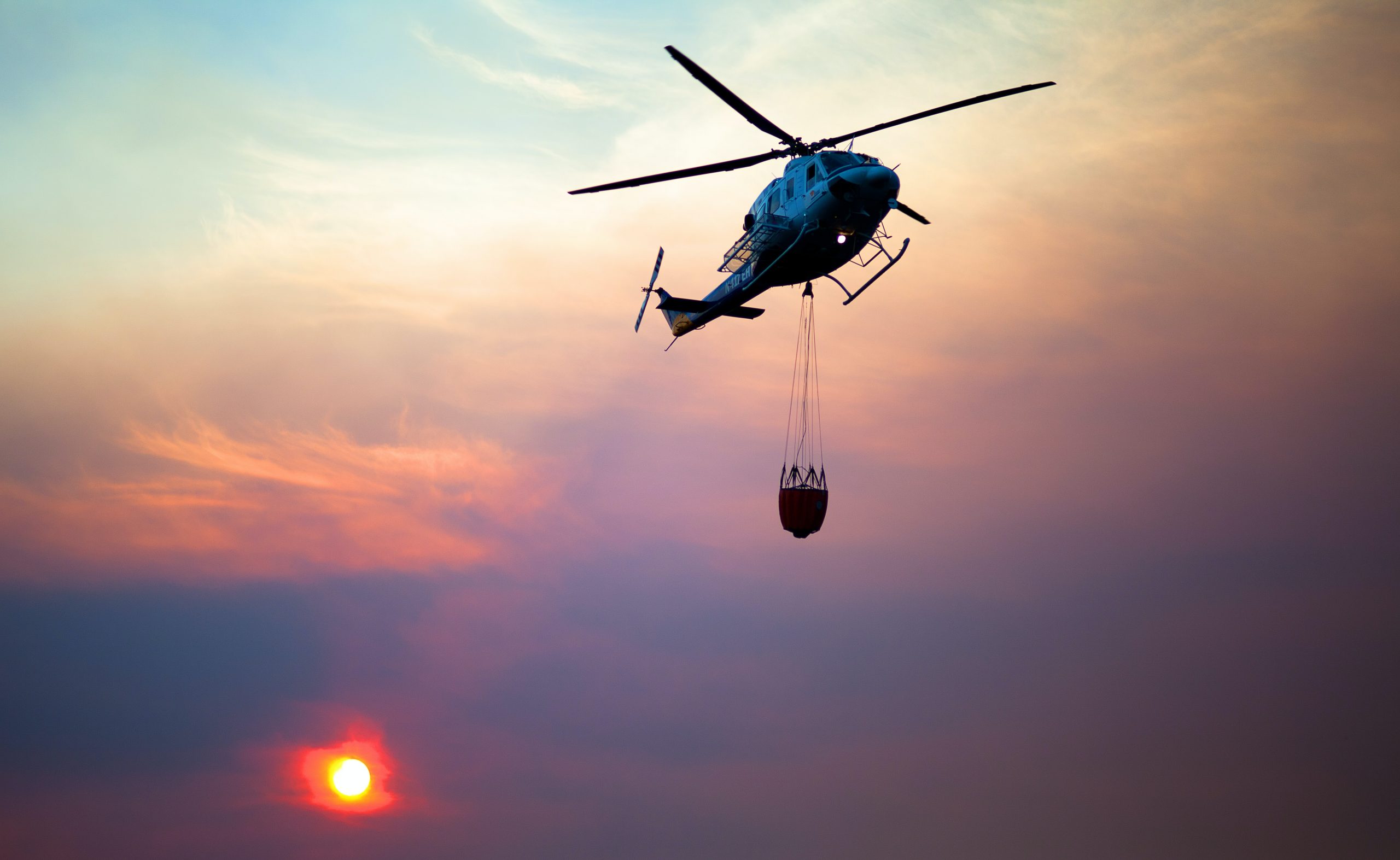
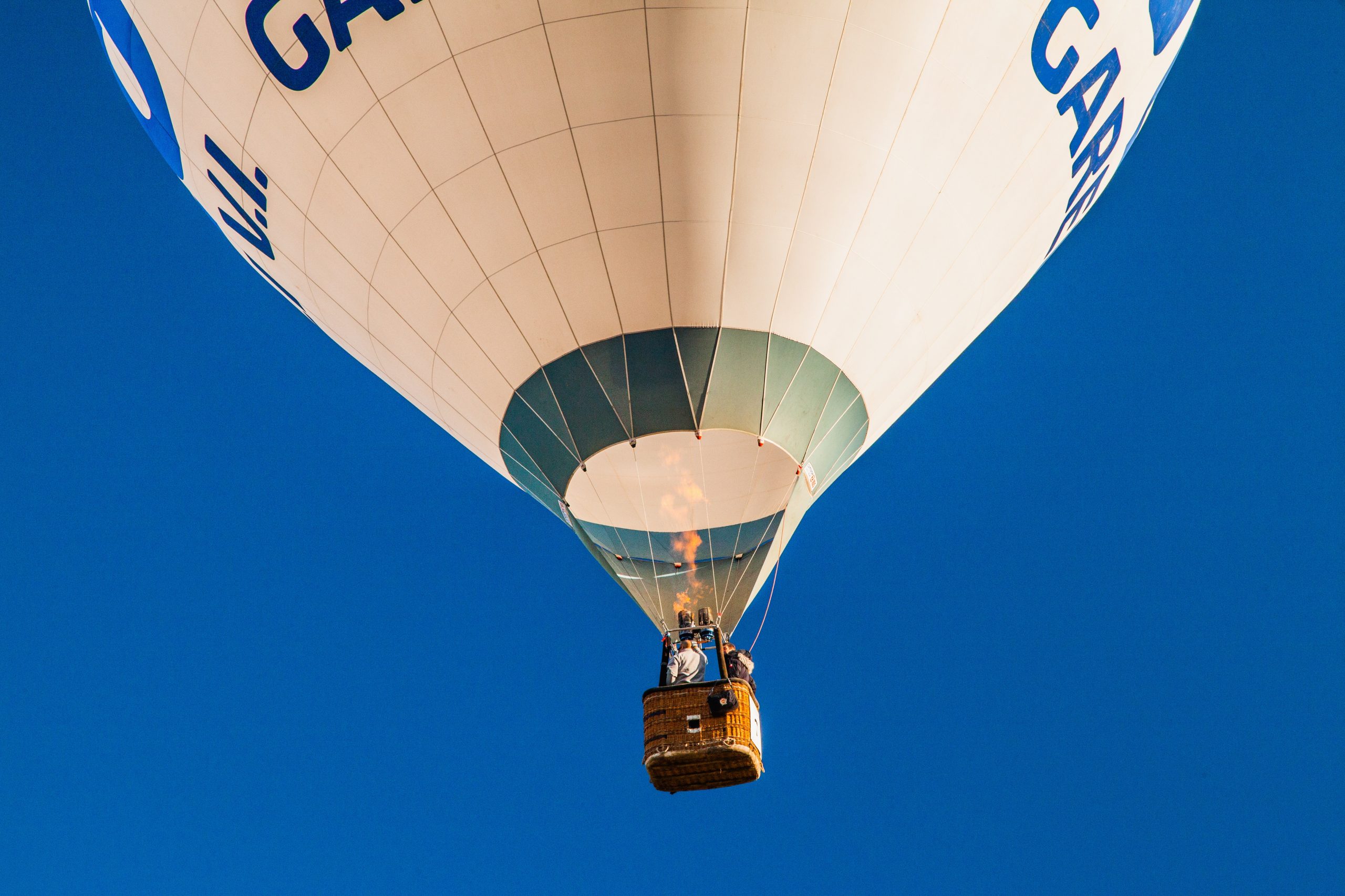
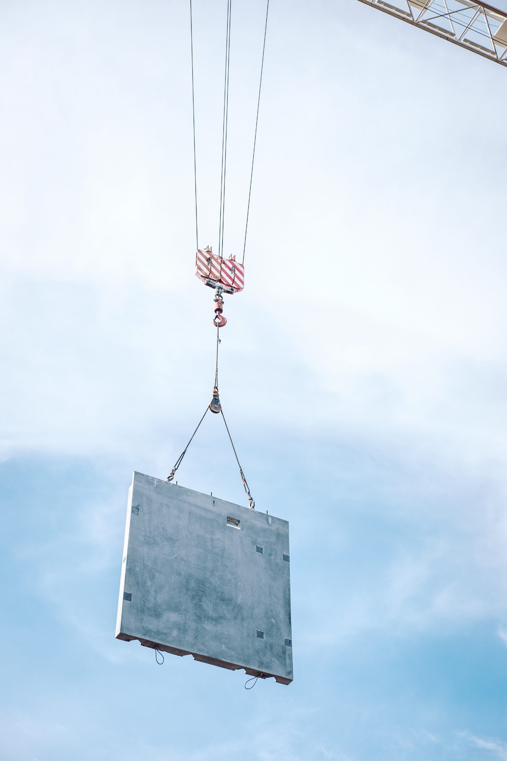
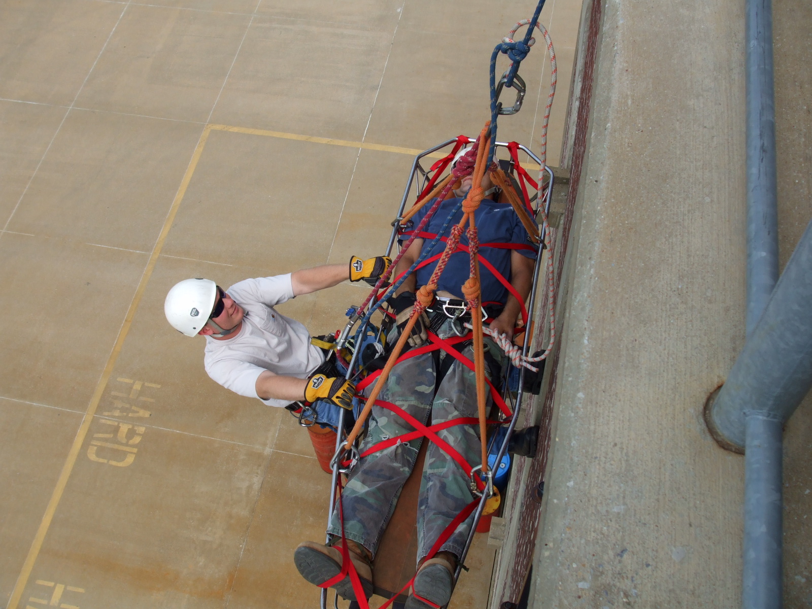
Figure 1: Forces that keep suspended objects in equilibrium apply to many everyday situationsLet’s look at some examples of how this type of problem applies in practice.
Example 3.1
This sign hangs in a shop window as shown. It is perfectly balanced. Each cable is at an angle of [latex]\scriptsize 65^\circ[/latex] to the horizontal and experiences a tension force of [latex]\scriptsize 2.5\text{ N}[/latex].
- What is the size of the downward force acting on the sign?
- What is the mass of the sign?

Solution
- Start by drawing a force diagram to show the forces in the system.
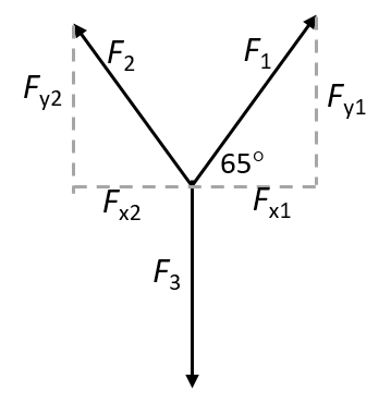
The system is in equilibrium, which means all the forces must be balanced. Therefore, the downward force acting on the sign must be balanced by the upward forces exerted by the cables.
Therefore [latex]\scriptsize {{F}_{{y1}}}+{{F}_{{y2}}}={{F}_{3}}[/latex].
.
Because the angles of the cables are the same, [latex]\scriptsize {{F}_{{y1}}}={{F}_{{y2}}}[/latex], we can write [latex]\scriptsize 2{{F}_{{y1}}}={{F}_{3}}[/latex].
To find [latex]\scriptsize {{F}_{{y1}}}[/latex]:
[latex]\scriptsize \displaystyle \begin{align*}\displaystyle \frac{{{{F}_{{y1}}}}}{{{{F}_{1}}}}&=\sin 65^\circ \\{{F}_{{y1}}}&=2.27\text{ N}\end{align*}[/latex]
.
Therefore [latex]\scriptsize {{F}_{3}}=2(2.27)=4.54\text{ N}[/latex]. - We know that F3 is the weight of the sign: [latex]\scriptsize {{F}_{3}}=mg[/latex].
To determine its mass, we rearrange the equation:
[latex]\scriptsize m=\displaystyle \frac{{{{F}_{3}}}}{{9.8}}=0.46\text{ kg}[/latex]
Example 3.2
Example taken from Chapter 4 in OpenStax Physics, p. 174 released under a CC-BY licence
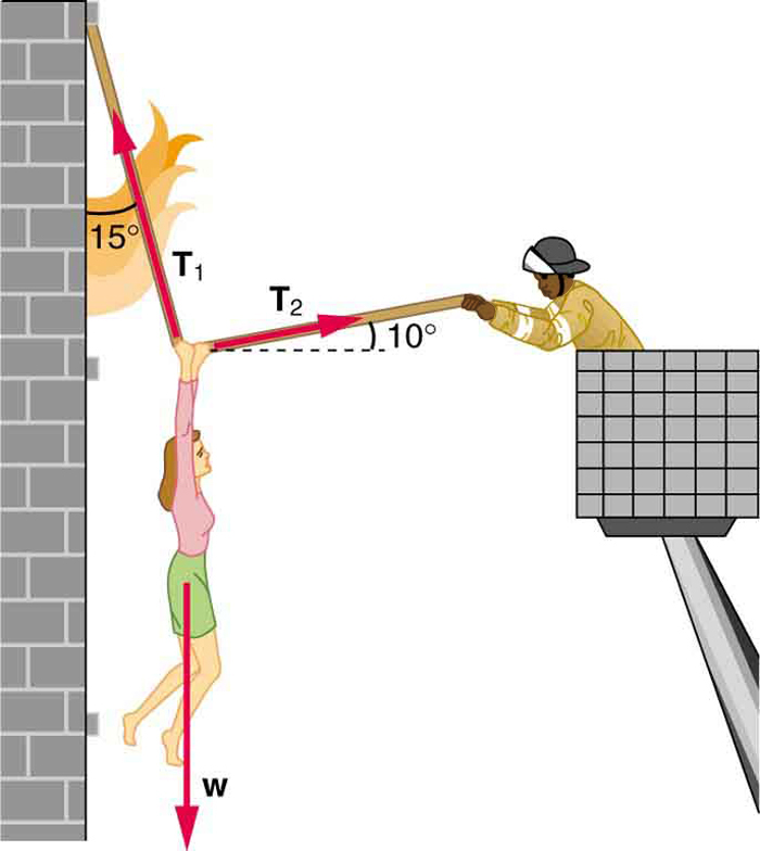
A person of [latex]\scriptsize 76\text{ kg}[/latex] is being pulled away from a burning building as shown in the diagram.
- Calculate the tension in the two ropes if the person is momentarily motionless. Include a free-body diagram in your solution.
- Explain how you can check your reasoning.
Solution
- Start by drawing a force diagram to show the forces in the system.
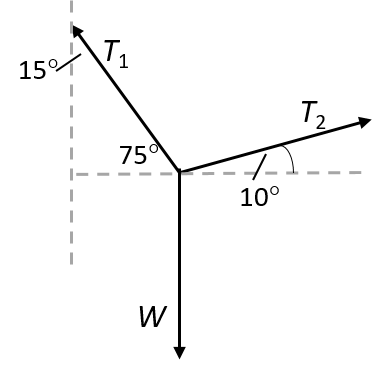
We can then calculate the forces. [latex]\scriptsize \displaystyle {{T}_{1}}[/latex] makes an angle of [latex]\scriptsize \displaystyle 15^\circ[/latex] with the wall, so the angle with the horizontal is [latex]\scriptsize \displaystyle 75^\circ[/latex].[latex]\scriptsize \displaystyle \begin{align*}\displaystyle \frac{{{{T}_{{x1}}}}}{{{{T}_{1}}}}&=\cos 75^\circ \\\therefore {{T}_{{x1}}}&={{T}_{1}}(\cos 75^\circ )\\{{T}_{{x1}}}&={{T}_{1}}(0.2588)\end{align*}[/latex] AND [latex]\scriptsize \displaystyle \begin{align*}\displaystyle \frac{{{{T}_{{x2}}}}}{{{{T}_{2}}}}&=\cos 10^\circ \\\therefore {{T}_{{x2}}}&={{T}_{2}}(\cos 10^\circ )\\{{T}_{{x2}}}&={{T}_{2}}(0.9848)\end{align*}[/latex] .
Because the system is in equilibrium, the horizontal forces balance each other out, and we can therefore solve for [latex]\scriptsize \displaystyle {{T}_{1}}[/latex] in terms of [latex]\scriptsize \displaystyle {{T}_{2}}[/latex].[latex]\scriptsize \displaystyle \begin{align*}\displaystyle \frac{{{{T}_{{y1}}}}}{{{{T}_{1}}}}&=\sin 75^\circ \\\therefore {{T}_{{y1}}}&={{T}_{1}}(\sin 75^\circ )\\&={{T}_{1}}(0.9659)\\&=(3.805{{T}_{2}})(0.9659)\\&=3.6753{{T}_{2}}\end{align*}[/latex] AND [latex]\scriptsize \displaystyle \begin{align*}\displaystyle \frac{{{{T}_{{y2}}}}}{{{{T}_{2}}}}&=\sin 10^\circ \\\therefore {{T}_{{y2}}}&={{T}_{2}}(\sin 10^\circ )\\{{T}_{{y2}}}&=0.1736{{T}_{2}}\end{align*}[/latex] .
[latex]\scriptsize \displaystyle \begin{align*}{{T}_{{y1}}}+{{T}_{{y2}}}&=W\\\therefore {{T}_{{y1}}}+{{T}_{{y2}}}&=76\times 9.8=744.8\text{ N}\\\text{3}.6753{{T}_{2}}+0.1736{{T}_{2}}&=744.8\ \text{N}\\\therefore {{T}_{2}}&=193.51\ \text{N}\end{align*}[/latex]
.
[latex]\scriptsize \displaystyle \begin{align*}{{T}_{1}}&=3.805{{T}_{2}}\\\therefore {{T}_{1}}&=3.805(193.51)\\&=736.30\text{ N}\end{align*}[/latex] - The force needed to hold steady the person being rescued from the fire, [latex]\scriptsize {{T}_{2}}[/latex], is less than her weight and less than the force [latex]\scriptsize {{T}_{1}}[/latex] in the other rope as the more vertical rope supports a greater part of her weight (a vertical force).
Exercise 3.1
Questions 1 and 2 taken from Exercise 1-7 in the Siyavula Gr 11 Physical Science Learner’s Book on pp. 50–53, released under a CC-BY licence
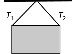
- An object of weight [latex]\scriptsize W[/latex] is supported by two cables attached to the ceiling and wall as shown.

The tensions in the two cables are [latex]\scriptsize \displaystyle {{T}_{1}}[/latex] and [latex]\scriptsize \displaystyle {{T}_{2}}[/latex], respectively. [latex]\scriptsize \displaystyle {{T}_{1}}=1200\text{ N}[/latex].- Determine the tension [latex]\scriptsize \displaystyle {{T}_{2}}[/latex] by construction and measurement.
- Determine the tension [latex]\scriptsize \displaystyle {{T}_{2}}[/latex] by calculation.
- Determine the mass of object [latex]\scriptsize W[/latex].
- Compare the mass as determined by calculation and construction. Give a reason for your answer.
- An object X is supported by two strings, A and B, attached to the ceiling as shown in the sketch. Each [latex]\scriptsize \displaystyle {{T}_{2}}[/latex] of these strings can withstand a maximum force of [latex]\scriptsize \displaystyle 700\text{ N}[/latex]. The weight of X is increased gradually.
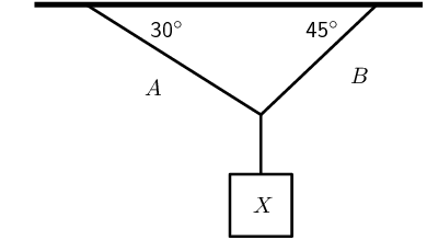
- Draw a rough sketch of the triangle of forces, and use it to explain which string will break first.
- Determine the maximum weight of X which can be supported.
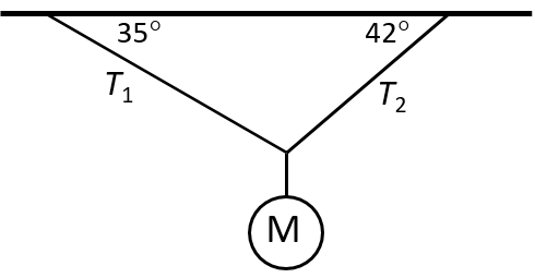
- A mirror ball (mass = [latex]\scriptsize 6.6\text{ kg}[/latex]) is suspended by two cables attached to a ceiling as shown. Determine the tensions in [latex]\scriptsize \displaystyle {{T}_{1}}[/latex] and .
The full solutions are at the end of the unit.
Objects on an inclined plane
An inclined plane is a surface that is at angle with the horizontal, in other words a slope. Objects placed on an inclined plane will slide down the surface if the forces acting on it are unbalanced. Similarly, if all forces are balanced, the object can be kept stationary. To calculate the forces governing an object’s behaviour on an inclined plane, we have to resolve forces into their components.
Example 3.3
Example taken from Siyavula Gr 11 Physical Science Learner’s Book on p. 71, Example 6, released under a CC-BY licence
A block on an inclined plane experiences a force due to gravity, [latex]\scriptsize \displaystyle {{F}_{g}}=137\text{ N}[/latex] straight down. If the slope is inclined at [latex]\scriptsize \displaystyle 37^\circ[/latex] to the horizontal, what is the component of the force due to gravity perpendicular and parallel to the slope?
Solution
We know that for a block on a slope we can resolve the force due to gravity, [latex]\scriptsize \displaystyle {{F}_{g}}[/latex], into components parallel and perpendicular to the slope:

- Parallel component: [latex]\scriptsize \displaystyle {{F}_{{gx}}}={{F}_{g}}\sin 37^\circ[/latex]
- Perpendicular component: [latex]\scriptsize \displaystyle {{F}_{{gy}}}={{F}_{g}}\cos 37^\circ[/latex]
Therefore:
[latex]\scriptsize \displaystyle \begin{align*}{{F}_{{gx}}}&={{F}_{g}}\sin 37^\circ \\&=(137)(\sin 37^\circ )\\&=82.45\text{ N in the negative }x\text{-direction}\text{.}\end{align*}[/latex]
[latex]\scriptsize \displaystyle \begin{align*}{{F}_{{gy}}}&={{F}_{g}}\cos 37^\circ \\&=(137)(\cos 37^\circ )\\&=109.41\ \text{N in the negative }y\text{-direction}\text{.}\end{align*}[/latex]
Example 3.4
Example taken from Siyavula Gr 11 Physical Science Learner’s Book on pp. 92-93, Example 15, released under a CC-BY licence
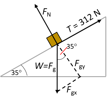
A force of magnitude [latex]\scriptsize \displaystyle T=312\text{ N}[/latex] up an incline is required to keep a body at rest on a frictionless inclined plane which makes an angle of [latex]\scriptsize \displaystyle 35^\circ[/latex] with the horizontal. Calculate:
- the force due to gravity
- the normal force.
Solutions
Define upwards as the positive y-direction and to the right as the positive x-direction.
- For the force due to gravity:
[latex]\scriptsize \displaystyle \begin{align*}{{F}_{{gx}}}&={{F}_{g}}\sin 35^\circ \\{{F}_{{gx}}}+T&=0\\\therefore {{F}_{g}}\sin 35^\circ &=-312\text{ N}\\\therefore {{F}_{g}}&=543.96\ \text{N downwards}\end{align*}[/latex] - We know that the normal force is the opposite of the perpendicular component of [latex]\scriptsize \displaystyle {{F}_{g}}[/latex]. We can use the given angle and [latex]\scriptsize \displaystyle {{F}_{g}}[/latex] as calculated to determine this component, and by implication the normal force, [latex]\scriptsize \displaystyle {{F}_{\text{N}}}[/latex].
However, to keep the calculation dependent only on given values (in case our calculation of [latex]\scriptsize \displaystyle {{F}_{g}}[/latex] was incorrect), we can use the angle only. We know that [latex]\scriptsize \displaystyle T=312\ \text{N = }{{F}_{g}}\sin 35^\circ[/latex] and [latex]\scriptsize \displaystyle {{F}_{\text{N}}}={{F}_{g}}\cos 35^\circ[/latex].
Recall further from trigonometry that [latex]\scriptsize \displaystyle \frac{{\sin \theta }}{{\cos \theta }}=\tan \theta[/latex].
Therefore:
[latex]\scriptsize \begin{align*}\displaystyle \frac{{{{F}_{g}}\sin 35^\circ }}{{{{F}_{g}}\cos 35^\circ }}&=\tan 35^\circ \\\therefore {{F}_{\text{N}}}&=\displaystyle \frac{T}{{\tan 35^\circ }}\\&=445.58\ \text{N}\end{align*}[/latex]
We can double check our answers (for both [latex]\scriptsize \displaystyle {{F}_{g}}[/latex] and its perpendicular component) by using the value of [latex]\scriptsize \displaystyle {{F}_{g}}[/latex] calculated earlier.
Exercise 3.2
Questions taken from Siyavula Gr 11 Physical Science Learner’s Book on pp. 120–131, Exercise 2-10, released under a CC-BY licence
- A stationary block of mass [latex]\scriptsize \displaystyle 3\ \text{kg}[/latex] is on top of a plane inclined at [latex]\scriptsize \displaystyle 55^\circ[/latex] to the horizontal.
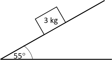
- Draw a force diagram (not to scale). Include the weight of the block as well as the components of the weight that are perpendicular and parallel to the inclined plane.
- Determine the values of the weight’s perpendicular and parallel components.
- An elephant is being moved from the Kruger National Park to the Eastern Cape. It is loaded into a crate that is pulled up a ramp (an inclined plane) on frictionless rollers. The diagram shows the crate being held stationary on the ramp by means of a rope parallel to the ramp. The tension in the rope is [latex]\scriptsize 5000\text{ N}[/latex].
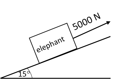
- Draw a labelled free-body diagram of the forces acting on the elephant. (Regard the crate and elephant as one object, and represent them as a dot. Also show the relevant angles between the forces.)
- The crate has a mass of [latex]\scriptsize 800\text{ kg}[/latex]. Determine the mass of the elephant.
The full solutions are at the end of the unit.
Working with friction
arises where two surfaces are in contact and moving relative to each other. When the surface of one object slides over the surface of another, each body exerts a frictional force on the other. For example, if a book slides across a table, the table exerts a frictional force onto the book and the book exerts a frictional force onto the table. Frictional force acts parallel to the surface.
Frictional force ([latex]\scriptsize {{F}_{{\text{friction}}}}[/latex]) is the force that opposes the motion of an object in contact with a surface and it acts parallel to the surface the object is in contact with.
The magnitude of the frictional force depends on the surface and the magnitude of the normal force ([latex]\scriptsize {{F}_{\text{N}}}[/latex] – the force exerted perpendicularly by a surface on an object in contact with it). Different surfaces will give rise to different frictional forces, even if the normal force is the same. A frictional force is therefore proportional to the magnitude of the normal force: [latex]\scriptsize {{F}_{{\text{friction}}}}\propto {{F}_{\text{N}}}[/latex].
Take note!
Frictional force can also be written as [latex]\scriptsize f[/latex] or [latex]\scriptsize {{F}_{{\text{fr}}}}[/latex].
For every surface we can determine a constant factor – called the coefficient of friction – which allows us to calculate what the frictional force would be if we know the magnitude of the normal force. Static friction and kinetic friction have different magnitudes, so we have different coefficients for the two types of friction:
- [latex]\scriptsize \displaystyle {{\mu }_{s}}[/latex] is the coefficient of static friction
- [latex]\scriptsize \displaystyle {{\mu }_{k}}[/latex] is the coefficient of kinetic friction.
Take note!
Remember that the coefficients of friction are unitless quantities.
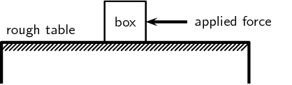
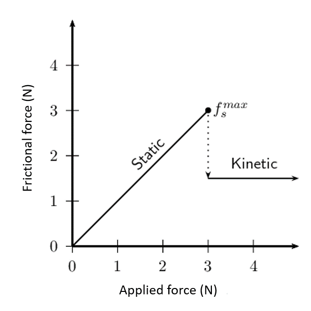
Static friction
A force is not always large enough to make an object move. For example, a small applied force might not be able to move a heavy crate. The frictional force opposing the motion of the crate is equal to the applied force but acting in the opposite direction. This frictional force is called ([latex]\scriptsize \displaystyle {{f}_{s}}[/latex]). Static friction can vary from zero (when no other forces are present and the object is stationary) to a maximum, which depends on the characteristics of the two surfaces. The maximum value for the static friction: [latex]\scriptsize \displaystyle f_{s}^{{\max }}={{\mu }_{s}}{{F}_{\text{N}}}[/latex].
Kinetic friction
When the applied force is greater than the maximum static frictional force, the object moves but still experiences friction. This is called ([latex]\scriptsize \displaystyle {{f}_{k}}[/latex]). The value of kinetic friction remains the same regardless of the magnitude of the applied force. The magnitude of the kinetic friction is given by: [latex]\scriptsize \displaystyle {{f}_{k}}={{\mu }_{k}}{{F}_{\text{N}}}[/latex].
Take note!
Remember that static friction is present when an object is not moving, and kinetic friction while the object is moving. For example, when you drive at constant velocity in a car on a tar road, you have to keep the accelerator pushed in slightly to overcome the friction between the tar road and the wheels of the car. However, while moving at a constant velocity the wheels of the car are rolling, so this is not a case of two surfaces ‘rubbing’ against each other and we are, in fact, looking at static friction. If you were to break hard, causing the car to skid to a halt, we would be dealing with two surfaces rubbing against each other, and hence kinetic friction. The higher the value for the coefficient of friction, the more ‘sticky’ the surface is and the lower the value, the more ‘slippery’ the surface is.
Example 3.5
Example taken from Siyavula Gr 11 Physical Science Learner’s Book on pp. 62-63, Example 1, released under a CC-BY licence
A box resting on a surface experiences a normal force, [latex]\scriptsize {{F}_{\text{N}}}[/latex], of magnitude [latex]\scriptsize 30\text{ N}[/latex] and the coefficient of static friction between the surface and the box, [latex]\scriptsize {{\mu }_{s}}[/latex], is [latex]\scriptsize 0.34[/latex]. What is the maximum static frictional force?
Solution
We know that the relationship between the maximum static friction, the coefficient of static friction and the normal force to be:
[latex]\scriptsize \displaystyle f_{s}^{{\max }}={{\mu }_{s}}{{F}_{\text{N}}}[/latex]
We have been given that [latex]\scriptsize {{\mu }_{s}}=0.34[/latex] and [latex]\scriptsize {{F}_{\text{N}}}=30\text{ N}[/latex]. Therefore:
[latex]\scriptsize \displaystyle \begin{align*}f_{s}^{{\max }}&={{\mu }_{s}}{{F}_{\text{N}}}\\&=(0.34)(30)\\&=10.2\text{ N}\end{align*}[/latex]
Example 3.6
Example taken from Siyavula Gr 11 Physical Science Learner’s Book on pp. 64-65, Example 3, released under a CC-BY licence
The normal force exerted on a pram is [latex]\scriptsize 100\text{ N}[/latex]. The pram’s brakes are locked so that the wheels cannot turn. The owner tries to push the pram but it does not move. The owner pushes harder and harder until the pram suddenly starts to move when the applied force is three-quarters of the normal force. After that, the owner is able to keep it moving with a force that is half of the force at which it started moving.
- What is the magnitude of the applied force at which the pram starts moving?
- What are the coefficients of (a) static and (b) kinetic friction?
Solutions
- The owner of the pram increases the force he is applying until the pram suddenly starts to move. This will be equal to the maximum static friction, which we know is given by: [latex]\scriptsize \displaystyle f_{s}^{{\max }}={{\mu }_{s}}{{F}_{\text{N}}}[/latex].
The magnitude of the applied force is three-quarters of the normal force. So:
[latex]\scriptsize \displaystyle \begin{align*}f_{s}^{{\max }}&=\displaystyle \frac{3}{4}{{F}_{\text{N}}}\\&=\displaystyle \frac{3}{4}(100)\\&=75\text{ N}\end{align*}[/latex]
The applied force at which static friction is overcome, and so allows the pram to start moving, is [latex]\scriptsize 75\text{ N}[/latex]. - .
- We now know both the maximum magnitude of static friction and the magnitude of the normal force, and so we can find the coefficient of static friction:
[latex]\scriptsize \displaystyle \begin{align*}f_{s}^{{\max }}&={{\mu }_{s}}{{F}_{\text{N}}}\\75&={{\mu }_{s}}(100)\\{{\mu }_{s}}&=0.75\end{align*}[/latex] - The magnitude of the force required to keep the pram moving is half of the force required to get it to start moving. Therefore:
[latex]\scriptsize \displaystyle \begin{align*}{{f}_{k}}&=\displaystyle \frac{1}{2}f_{s}^{{\max }}\\&=\displaystyle \frac{1}{2}(75)\\&=37.5\ \text{N}\end{align*}[/latex]
.
We know the relationship between the magnitude of the kinetic friction, magnitude of the normal force and coefficient of kinetic friction. We can use it to solve for the coefficient of kinetic friction:
[latex]\scriptsize \displaystyle \begin{align*}{{f}_{k}}&={{\mu }_{k}}{{F}_{\text{N}}}\\37.5&={{\mu }_{k}}(100)\\{{\mu }_{k}}&=0.375\end{align*}[/latex]
- We now know both the maximum magnitude of static friction and the magnitude of the normal force, and so we can find the coefficient of static friction:
Exercise 3.3
Questions taken from Exercise 2-1 in the Siyavula Gr 11 Physical Science Learner’s Book on p. 67, released under a CC-BY licence
- A box is placed on a rough surface. It has a normal force of magnitude [latex]\scriptsize 120\text{ N}[/latex]. A force of [latex]\scriptsize 20\text{ N}[/latex] applied to the right cannot move the box. Calculate the magnitude and direction of the friction forces.
- A block rests on a horizontal surface. The normal force is [latex]\scriptsize 20\text{ N}[/latex]. The coefficient of static friction between the block and the surface is [latex]\scriptsize 0.40[/latex] and the coefficient of kinetic friction is [latex]\scriptsize 0.20[/latex].
- What is the magnitude of the frictional force exerted on the block while the block is at rest?
- What will the magnitude of the frictional force be if a horizontal force of magnitude [latex]\scriptsize 5\text{ N}[/latex] is exerted on the block?
- What is the minimum force required to start the block moving?
- What is the minimum force required to keep the block in motion once it has been started?
- If the horizontal force is [latex]\scriptsize 10\text{ N}[/latex], determine the frictional force.
The full solutions are at the end of the unit.
Summary
In this unit you have learnt the following:
- In a system in which an object is stationary (at rest), all the forces acting concurrently on the object are balanced. This means the system is in equilibrium.
- An inclined plane is a surface that makes an angle with the horizontal.
- The behaviour of an object on an inclined plane is determined by whether the forces acting on it are balanced or unbalanced.
- If the forces are unbalanced, the object will slide down the surface.
- If the forces are balanced, the object will remain at rest.
- To calculate the forces acting concurrently on an object on an inclined plane or hanging on ropes, we must resolve the diagonal forces into components.
- Friction is a force that resists motion. Friction occurs when two surfaces are in contact and moving relative to each other.
- Friction acts parallel to the surface the object is in contact with.
- Static friction is the frictional force that exists between an object and a surface before the object starts moving.
- The maximum value for the static friction: [latex]\scriptsize \displaystyle f_{s}^{{\max }}={{\mu }_{s}}{{F}_{\text{N}}}[/latex].
- Kinetic friction is the frictional force that occurs when an object moves over a surface.
- The magnitude of the kinetic friction is: [latex]\scriptsize \displaystyle {{f}_{k}}={{\mu }_{k}}{{F}_{\text{N}}}[/latex].
Unit 3: Assessment
Suggested time to complete: 60 minutes
Questions 1, 5–7, 8 and 9 are taken from Chapter 2 in the Siyavula Gr 11 Physical Science Learner’s Book, pp. 56-133 released under a CC-BY licence
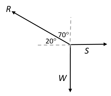
- A heavy box, mass m, is lifted by means of a rope R, which passes over a pulley fixed to a pole. A second rope, S, is tied to rope R at point P and exerts a horizontal force that pulls the box to the right. After lifting the box to a certain height, the box is held stationary as shown in the diagram. Ignore the masses of the ropes. The tension in rope R is [latex]\scriptsize 5850\text{ N}[/latex].
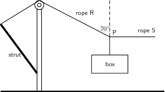
By resolving the force exerted by rope R into components, calculate the:- magnitude of the force exerted by rope S
- mass, m, of the box.
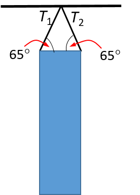
- A punching bag of mass [latex]\scriptsize 60\text{ kg}[/latex] is attached to a point on a ceiling by two cables. What is the tension in each cable?
- An object of [latex]\scriptsize 14.6\text{ kg}[/latex] is supported by two cables of equal length. The cables are at an angle of [latex]\scriptsize 64.8^\circ[/latex] to each other. Determine the tension in each cable.
- A hammock is attached to two trees. The cable T1 is at an angle of [latex]\scriptsize 32^\circ[/latex]to the horizontal and experiences a tension force of [latex]\scriptsize 550\text{ N}[/latex]. The tension in cable T2 is [latex]\scriptsize 610\text{ N}[/latex]. What should the angle be between T2 and the tree so that the system will be in equilibrium when someone gets onto the hammock?

- A block on an inclined plane experiences a force due to gravity, [latex]\scriptsize {{F}_{g}}[/latex] of [latex]\scriptsize 300\text{ N}[/latex] straight down. If the slope is inclined at [latex]\scriptsize 67.8^\circ[/latex] to the horizontal, what is the component of the force due to gravity:
- perpendicular to the slope?
- parallel to the slope?
- A block on an inclined plane is subjected to a force due to gravity, [latex]\scriptsize {{F}_{g}}[/latex] of [latex]\scriptsize 287\text{ N}[/latex] straight down. If the component of the gravitational force parallel to the slope is [latex]\scriptsize {{F}_{{gx}}}=123.7\text{ N}[/latex] in the negative x-direction (down the slope), what is the incline of the slope?
- A block on an inclined plane experiences a force due to gravity, [latex]\scriptsize {{F}_{g}}[/latex] of [latex]\scriptsize \text{98 N}[/latex] straight down. If the slope is inclined at an unknown angle to the horizontal but we are told that the ratio of the components of the force due to gravity perpendicular and parallel to the slope is [latex]\scriptsize 7:4[/latex]. What is the angle the incline makes with the horizontal?
- The forwards of a rugby team are trying to push their scrum machine. The normal force exerted on the scrum machine is [latex]\scriptsize 10000\text{ N}[/latex]. The machine is not moving at all. If the coefficient of static friction is [latex]\scriptsize 0.78[/latex], what is the minimum force they need to exert to get the scrum machine moving?
- A [latex]\scriptsize 12\ \text{kg}[/latex] box is placed on a rough surface. A force of [latex]\scriptsize \text{20 N}[/latex] applied at an angle of [latex]\scriptsize 30^\circ[/latex] to the horizontal cannot move the box. Calculate the magnitude and direction of the:
- normal force
- friction forces.
The full solutions are at the end of the unit.
Unit 3: Solutions
Exercise 3.1
- .
- .
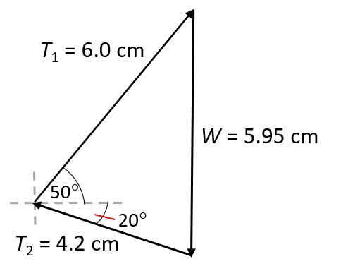
Scale: [latex]\scriptsize 1\text{ cm = 200 N}[/latex] - Draw a force diagram to visualise the problem.
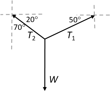
The system is in equilibrium so [latex]\scriptsize \sum {{T}_{x}}=0[/latex] and [latex]\scriptsize \sum {{T}_{y}}=0[/latex].
Therefore [latex]\scriptsize \displaystyle {{T}_{{x1}}}={{T}_{{x2}}}[/latex]
[latex]\scriptsize \displaystyle \begin{align*}{{T}_{{x1}}}&={{T}_{1}}\cos 50^\circ \\&=(1200)(0.643)\\&=771.35\text{ N}\end{align*}[/latex]
.
The system is in equilibrium so [latex]\scriptsize \sum {{T}_{x}}=0[/latex] and [latex]\scriptsize \sum {{T}_{y}}=0[/latex].
[latex]\scriptsize \begin{align*}{{T}_{{x1}}}&={{T}_{{x2}}}\\\therefore {{T}_{{x2}}}&=771.35\text{ N}\end{align*}[/latex]
.
[latex]\scriptsize \displaystyle \begin{align*}\displaystyle \frac{{{{T}_{{x2}}}}}{{{{T}_{2}}}}&=\cos 20^\circ \\\therefore {{T}_{2}}&=\displaystyle \frac{{{{T}_{{x2}}}}}{{\cos 20^\circ }}\\&=\displaystyle \frac{{771.35}}{{0.94}}\\&=820.59\text{ N}\end{align*}[/latex] - .
[latex]\scriptsize \begin{align*}\sum {{T}_{y}}&=0\\\therefore {{T}_{{y1}}}+{{T}_{{y2}}}&=-W\\({{T}_{1}}\sin 50^\circ )+({{T}_{2}}\sin 20^\circ )&=-W\\&=(1200\times 0.766)+(820.59\times 0.342)\\&=919.25+280.66\\&=1199.9\text{N}\\&\approx 1200\text{ N}\end{align*}[/latex]
Thus, [latex]\scriptsize \displaystyle W=1200\text{ N}[/latex] acting downwards, and to find the mass of object [latex]\scriptsize W[/latex]:
[latex]\scriptsize \displaystyle \begin{align*}W&=mg\\\therefore m&=\displaystyle \frac{W}{g}\\&=\displaystyle \frac{{1200}}{{9.8}}\\&=122.43\text{ kg}\end{align*}[/latex] - From the construction diagram, [latex]\scriptsize W[/latex] was measured as [latex]\scriptsize 5.95\text{ cm}[/latex]. Using a scale of [latex]\scriptsize 1\text{ cm = 200 N}[/latex], [latex]\scriptsize \displaystyle W=1190\text{ N}[/latex], and therefore its mass is determined as [latex]\scriptsize \displaystyle 121.43\text{ kg}[/latex] vs [latex]\scriptsize \displaystyle 122.43\text{ kg}[/latex] as determined by calculation. The discrepancy is due to the precision of the measuring tools.
- .
- .
- We draw a rough sketch:

We note that [latex]\scriptsize {{T}_{A}}\cos 30^\circ ={{T}_{B}}\cos 45^\circ[/latex]. Therefore:
[latex]\scriptsize \begin{align*}\displaystyle \frac{{{{T}_{A}}}}{{{{T}_{B}}}}&=\displaystyle \frac{{\cos 45^\circ }}{{\cos 30^\circ }}\\&=\displaystyle \frac{1}{{\sqrt{2}}}\times \displaystyle \frac{{\sqrt{3}}}{2}\\&\therefore \displaystyle \frac{{{{T}_{A}}}}{{{{T}_{B}}}}1\\&\therefore {{T}_{A}}{{T}_{B}}\end{align*}[/latex] The tension in B is greater and hence it will break first.</li> - As B will break first, the maximum weight that can be supported is when B is at tension of [latex]\scriptsize 700\text{ N}[/latex].
[latex]\scriptsize \displaystyle \begin{align*}\displaystyle \frac{{{{T}_{A}}}}{{{{T}_{B}}}}&=\displaystyle \frac{{\cos 45^\circ }}{{\cos 30^\circ }}\\\therefore {{T}_{A}}&=700\times \displaystyle \frac{{\cos 45^\circ }}{{\cos 30^\circ }}\\{{T}_{A}}&=572\text{ N}\\X&=\text{(}{{T}_{A}}\sin 30^\circ )+{{T}_{B}}\sin 45^\circ \\&=781\text{ N}\end{align*}[/latex]
- We draw a rough sketch:
- .
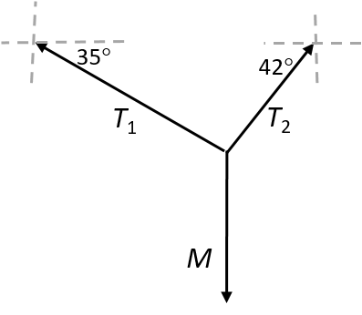
The system is in equilibrium so [latex]\scriptsize \sum {{T}_{x}}=0[/latex] and [latex]\scriptsize \sum {{T}_{y}}=0[/latex].
[latex]\scriptsize \displaystyle {{T}_{{x1}}}={{T}_{1}}\cos 35^\circ[/latex] and [latex]\scriptsize \displaystyle {{T}_{{x2}}}={{T}_{2}}\cos 42^\circ[/latex].
Because [latex]\scriptsize \sum {{T}_{x}}=0[/latex] we can write:
[latex]\scriptsize \displaystyle \begin{align*}{{T}_{1}}\cos 35^\circ &={{T}_{2}}\cos 42^\circ \\{{T}_{1}}\times 0.819&={{T}_{2}}\times 0.743\\\therefore {{T}_{2}}&=(\displaystyle \frac{{0.819}}{{0.743}}){{T}_{1}}\\\therefore {{T}_{2}}&=1.102({{T}_{1}})\end{align*}[/latex]
.
We know that [latex]\scriptsize {{T}_{{y1}}}+{{T}_{{y2}}}=W=mg[/latex] and [latex]\scriptsize mg=6.6\times 9.8=64.68\text{ N}[/latex].
[latex]\scriptsize \begin{align*}\therefore {{T}_{{y1}}}+{{T}_{{y2}}}&=64.68\text{ N}\\{{T}_{1}}\sin 35^\circ +{{T}_{2}}\sin 42^\circ &=64.68\text{ N}\\({{T}_{1}}\times 0.574)+[(1.102{{T}_{1}})(0.669)]&=64.68\text{ N}\\{{T}_{1}}(0.574)+{{T}_{1}}(0.737)&=64.68\text{ N}\\{{T}_{1}}(1.311)&=64.68\text{ N}\\{{T}_{1}}&=49.34\text{ N}\end{align*}[/latex]
.
To calculate T2:
[latex]\scriptsize \begin{align*}{{T}_{2}}&={{T}_{1}}\times 1.102\\&=(49.34)(1.102)\\&=54.37\text{ N}\end{align*}[/latex]
Exercise 3.2
- .
- The force diagram for the problem is as follows:
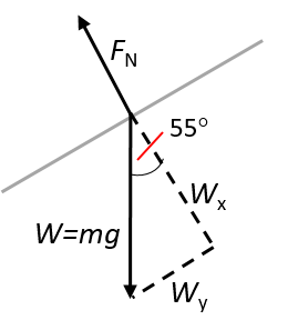
- For the component of the weight [latex]\scriptsize W[/latex] perpendicular to the slope:
[latex]\scriptsize \begin{align*}\displaystyle \frac{{{{W}_{x}}}}{W}&=\cos 55^\circ \\\therefore {{W}_{x}}&=W\cos 55^\circ \\&=(3\times 9.8)\cos 55^\circ \\&=16.86\text{ N}\end{align*}[/latex]
.
For the component of the weight [latex]\scriptsize W[/latex] parallel to the slope:
[latex]\scriptsize \begin{align*}\displaystyle \frac{{{{W}_{y}}}}{W}&=\sin 55^\circ \\\therefore {{W}_{y}}&=W\sin 55^\circ \\&=(3\times 9.8)\sin 55^\circ \\&=24.08\text{ N}\end{align*}[/latex]
- The force diagram for the problem is as follows:
- .
- .
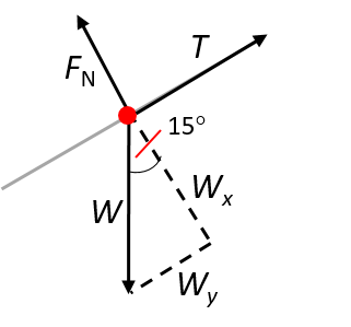
- In the diagram: [latex]\scriptsize {{W}_{y}}={{W}_{\parallel }}\text{ ; }{{W}_{x}}={{W}_{\bot }}[/latex]
[latex]\scriptsize \displaystyle \begin{align*}{{W}_{\parallel }}&=T=W\sin 15^\circ \\\therefore W&=\displaystyle \frac{{5000}}{{\sin 15^\circ }}\\&=19318.52\text{ N}\end{align*}[/latex]
.
We know that [latex]\scriptsize W[/latex] represents the force due to the combined mass of the crate and the elephant.
Therefore:
[latex]\scriptsize \begin{align*}({{m}_{{\text{crate}}}}+{{m}_{{\text{elephant}}}})&=\displaystyle \frac{W}{g}\\\therefore {{m}_{{\text{elephant}}}}&=\displaystyle \frac{W}{g}-{{m}_{{\text{crate}}}}\\&=\displaystyle \frac{{19318.52}}{{9.8}}-800\\&=1971.277-800\\&=1171.28\ \text{kg}\end{align*}[/latex]
- .
Exercise 3.3
- The normal force is given ([latex]\scriptsize 120\ \text{N}[/latex]) and we know that the block does not move when an applied force of [latex]\scriptsize 20\ \text{N}[/latex] is used.
We are asked to find the magnitude and direction of the friction forces. As the box is stationary and the applied force is insufficient to move the box, we know that the kinetic friction force is [latex]\scriptsize 0\ \text{N}[/latex].
The frictional force is defined as the force that opposes the motion of an object in contact with a surface and it acts parallel to the surface the object is in contact with. Therefore the static frictional force is [latex]\scriptsize 20\ \text{N}[/latex] to the left to give a resultant of zero. - .
- The block is not moving and so there is no kinetic frictional force acting on the block. There is also no force applied to the block and so the static frictional force is also zero.
- The block is not moving and so there is no kinetic frictional force acting on the block. The frictional force is defined as the force that opposes the motion of an object in contact with a surface and it acts parallel to the surface the object is in contact with. Therefore the static frictional force is [latex]\scriptsize 5\ \text{N}[/latex] in the opposite direction to the applied force.
- To find the minimum force required to start the block moving we need to calculate the maximum static friction force:
[latex]\scriptsize \displaystyle \begin{align*}f_{s}^{{\max }}&={{\mu }_{s}}{{F}_{\text{N}}}\\&=(0.40)(20)\\&=8\ \text{N}\end{align*}[/latex]
So we must apply a force of magnitude greater than [latex]\scriptsize 8\ \text{N}[/latex] to start the box moving. - To find the minimum force required to keep the block in motion we need to calculate the magnitude of the force of kinetic friction:
[latex]\scriptsize \displaystyle \begin{align*}{{f}_{k}}&={{\mu }_{k}}{{F}_{\text{N}}}\\&=(0.20)(20)\\&=4\ \text{N}\end{align*}[/latex]
So we must apply a force of [latex]\scriptsize 4\ \text{N}[/latex] to keep the box in motion. - This force is greater than the force required to start the block moving. So the static frictional force is [latex]\scriptsize 0\ \text{N}[/latex].
For kinetic friction, the value of the frictional force remains the same regardless of the magnitude of the applied force. So the kinetic frictional force is [latex]\scriptsize 4\ \text{N}[/latex].
Unit 3: Assessment
- Draw a force diagram to visualise the problem:
- .
[latex]\scriptsize \displaystyle \begin{align*}{{R}_{x}}&=S\\\displaystyle \frac{{{{R}_{x}}}}{R}&=\cos 20^\circ \\{{R}_{x}}&=R\cos 20^\circ \\&=5497.2\text{ N}\end{align*}[/latex] - .
[latex]\scriptsize \begin{align*}\displaystyle \frac{{{{R}_{y}}}}{R}&=\sin 20^\circ \\{{R}_{y}}&=R\sin 20^\circ \\&=5850\times 0.342\\&=2000.8\text{ N}\end{align*}[/latex]
.
Weight of box = mg
[latex]\scriptsize \begin{align*}\therefore m&=\displaystyle \frac{{2000.8}}{{9.8}}\\&=204.17\ \text{kg}\end{align*}[/latex]
- .
- Draw a force diagram to visualise the problem:

[latex]\scriptsize \begin{align*}W&=mg\\&=60\times 9.8\\&=588\text{ N}\end{align*}[/latex]
.
[latex]\scriptsize \begin{align*}{{T}_{{y\text{1}}}}+{{T}_{{y\text{2}}}}&=W\\{{T}_{{y1}}}&={{T}_{{y\text{2}}}}\\\therefore {{T}_{{y\text{1}}}}&=\displaystyle \frac{W}{2}\\&=\displaystyle \frac{{588}}{2}\\&=294\text{ N}\end{align*}[/latex]
.
[latex]\scriptsize \begin{align*}\displaystyle \frac{{{{T}_{{y\text{1}}}}}}{{{{T}_{1}}}}&=\sin 65^\circ \\\therefore T&=\displaystyle \frac{{{{T}_{{y\text{1}}}}}}{{\sin 65^\circ }}\\&=\displaystyle \frac{{294}}{{0.906}}\\&=324.50\ \text{N}\end{align*}[/latex] - Draw a force diagram to visualise the problem:
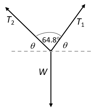
[latex]\scriptsize W=143.08\text{ N}[/latex]
[latex]\scriptsize \begin{align*}2\theta +64.8^\circ &=180^\circ \\\therefore \theta &=57.6^\circ \end{align*}[/latex]
.
Because [latex]\scriptsize {{T}_{{y1}}}={{T}_{{y2}}}[/latex] we can write:
[latex]\scriptsize \begin{align*}2{{T}_{{y1}}}&=W=143.08\text{ N}\\\therefore {{T}_{{y1}}}&=71.54\text{ N}\end{align*}[/latex]
[latex]\scriptsize \begin{align*}\displaystyle \frac{{{{T}_{{y1}}}}}{{{{T}_{1}}}}&=\sin 57.6^\circ \\\therefore {{T}_{1}}&=\displaystyle \frac{{{{T}_{{y1}}}}}{{\sin 57.6^\circ }}\\&=\displaystyle \frac{{71.54}}{{0.844}}\\&=84.76\text{ N}\\\therefore {{T}_{1}}&={{T}_{2}}=84.76\text{ N}\end{align*}[/latex] - Draw a force diagram to visualise the problem:
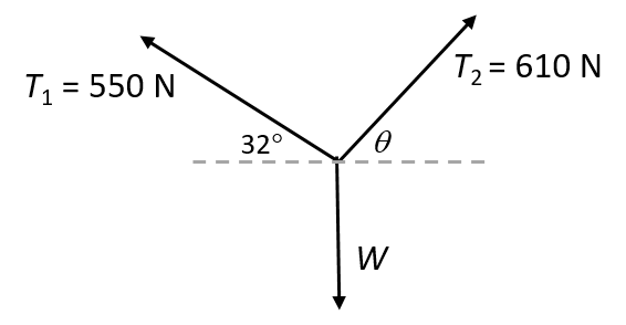
[latex]\scriptsize \displaystyle \begin{align*}{{T}_{{x1}}}&={{T}_{{x2}}}\\{{T}_{1}}\cos 32^\circ &={{T}_{2}}\cos \theta \\(550\times 0.848)&={{T}_{2}}\cos \theta \\466.43\text{ N}&={{T}_{2}}\cos \theta \\\cos \theta &=\displaystyle \frac{{466.43}}{{610}}\\\cos \theta &=0.765\\\therefore \theta &=40.13^\circ \end{align*}[/latex]
The angle between [latex]\scriptsize {{T}_{2}}[/latex] and the tree is therefore [latex]\scriptsize 90^\circ -40.13^\circ =49.87^\circ[/latex]. - Draw a diagram to visualise the problem:
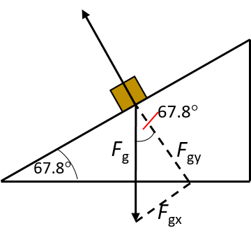
- For the perpendicular component of [latex]\scriptsize {{F}_{g}}[/latex]:
[latex]\scriptsize \begin{align*}{{F}_{{g\bot }}}&={{F}_{g}}(\cos 67.8^\circ )\\&=(300)(0.3778)\\&=113.35\ \text{N}\end{align*}[/latex] - For the parallel component of [latex]\scriptsize {{F}_{g}}[/latex]:
[latex]\scriptsize \begin{align*}{{F}_{{g\parallel }}}&={{F}_{g}}(\sin 67.8^\circ )\\&=(300)(0.92587)\\&=277.76\ \text{N}\end{align*}[/latex]
- For the perpendicular component of [latex]\scriptsize {{F}_{g}}[/latex]:
- Draw a diagram to visualise the problem:

[latex]\scriptsize \begin{align*}\sin \theta &=\displaystyle \frac{{{{F}_{{gx}}}}}{{{{F}_{g}}}}\\&=\displaystyle \frac{{123.7}}{{287}}=0.4310\\\therefore \theta &=25.53^\circ \end{align*}[/latex] - Draw a diagram to visualise the problem:

[latex]\scriptsize \begin{align*}{{F}_{{g\parallel }}}&={{F}_{g}}(\sin \theta )\\&=98\times \sin \theta \end{align*}[/latex] AND [latex]\scriptsize \begin{align*}{{F}_{{g\bot }}}&={{F}_{g}}(\cos \theta )\\&=98\times \cos \theta \end{align*}[/latex] We are told that: [latex]\scriptsize \displaystyle 7{{F}_{{g\parallel }}}=4{{F}_{{g\bot }}}[/latex]
Therefore:
[latex]\scriptsize \displaystyle \begin{align*}7(98)\sin \theta &=4(98)\cos \theta \\686\times \sin \theta &=392\times \cos \theta \\\displaystyle \frac{{\sin \theta }}{{\cos \theta }}&=\displaystyle \frac{{392}}{{686}}=0.5714\end{align*}[/latex]
.
Recall that: [latex]\scriptsize \displaystyle \displaystyle \frac{{\sin \theta }}{{\cos \theta }}=\tan \theta[/latex]
Therefore:
[latex]\scriptsize \displaystyle \begin{align*}\tan \theta &=0.5714\\\theta &=29.74^\circ \end{align*}[/latex] - The question asks what the minimum force will be to get the scrum machine moving. We do not know a relationship for this but we do know how to calculate the maximum force of static friction. The forwards need to exert a force greater than this, so the minimum amount they can exert is in fact equal to the maximum force of static friction.
.
[latex]\scriptsize \displaystyle \begin{align*}f_{s}^{{\max }}&={{\mu }_{s}}{{F}_{\text{N}}}\\&=(0.78)(10000)\\&=7800\ \text{N}\end{align*}[/latex] - .
- The normal force is equal in magnitude to the weight of the object. Therefore: [latex]\scriptsize {{F}_{\text{N}}}=mg=12(9.8)117.6\text{ N}[/latex]:
This force acts straight up from the surface. - The friction force is: [latex]\scriptsize {{F}_{{\text{friction}}}}={{F}_{{\text{app}}}}\cos 30^\circ =(20)\cos 30^\circ =17.3\text{ N}[/latex]
The frictional force acts in the opposite direction to the applied force.
- The normal force is equal in magnitude to the weight of the object. Therefore: [latex]\scriptsize {{F}_{\text{N}}}=mg=12(9.8)117.6\text{ N}[/latex]:
Media Attributions
- PS 3_2.2_3_Img01a © Artem Beliakin is licensed under a CC0 (Creative Commons Zero) license
- PS 3_2.2_3_Img01b © Victor Grabarczyk is licensed under a CC0 (Creative Commons Zero) license
- PS 3_2.2_3_Img01c © Gaetano Cessati is licensed under a CC0 (Creative Commons Zero) license
- PS 3_2.2_3_Img01d © Elvir K is licensed under a CC0 (Creative Commons Zero) license
- PS 3_2.2_3_Img01e © Jumper 5392 is licensed under a CC0 (Creative Commons Zero) license
- PS 3_2.2_3_Img02 © Victor Forgacs is licensed under a CC0 (Creative Commons Zero) license
- PS 3_2.2_3_Img03 © DHET is licensed under a CC BY (Attribution) license
- PS 3_2.2_3_Img04 © OpenStax/Rice University is licensed under a CC BY (Attribution) license
- PS 3_2.2_3_Img05 © DHET is licensed under a CC BY (Attribution) license
- PS 3_2.2_3_Img06 © DHET is licensed under a CC BY (Attribution) license
- PS 3_2.2_3_Img07 © Siyavula is licensed under a CC BY (Attribution) license
- PS 3_2.2_3_Img08 © DHET is licensed under a CC BY (Attribution) license
- PS 3_2.2_3_Img013 © DHET is licensed under a CC BY (Attribution) license
- PS 3_2.2_3_Img014 © DHET is licensed under a CC BY (Attribution) license
- PS 3_2.2_3_Img015 © DHET is licensed under a CC BY (Attribution) license
- PS 3_2.2_3_Img016New © DHET is licensed under a CC BY (Attribution) license
- PS 3_2.2_3_Img017 © Siyavula is licensed under a CC BY (Attribution) license
- PS 3_2.2_3_Img018 © DHET is licensed under a CC BY (Attribution) license
- PS 3_2.2_3_Img019 © Siyavula is licensed under a CC BY (Attribution) license
- PS 3_2.2_3_Img020 © DHET is licensed under a CC BY (Attribution) license
- PS 3_2.2_3_Img021 © DHET is licensed under a CC BY (Attribution) license
- PS 3_2.2_3_Img022 © DHET is licensed under a CC BY (Attribution) license
- PS 3_2.2_3_Img09 © DHET is licensed under a CC BY (Attribution) license
- PS 3_2.2_3_Img010 © DHET is licensed under a CC BY (Attribution) license
- PS 3_2.2_3_Img011 © DHET is licensed under a CC BY (Attribution) license
- PS 3_2.2_3_Img012 © DHET is licensed under a CC BY (Attribution) license
- PS 3_2.2_3_Img023 © DHET is licensed under a CC BY (Attribution) license
- PS 3_2.2_3_Img024 © DHET is licensed under a CC BY (Attribution) license
- PS 3_2.2_3_Img025 © DHET is licensed under a CC BY (Attribution) license
- PS 3_2.2_3_Img026 © DHET is licensed under a CC BY (Attribution) license
- PS 3_2.2_3_Img027 © DHET is licensed under a CC BY (Attribution) license
- PS 3_2.2_3_Img028 © DHET is licensed under a CC BY (Attribution) license
- PS 3_2.2_3_Img029 © DHET is licensed under a CC BY (Attribution) license
- PS 3_2.2_3_Img030 © DHET is licensed under a CC BY (Attribution) license
- PS 3_2.2_3_Img031 © DHET is licensed under a CC BY (Attribution) license
- Parts of the text in this unit were sourced or adapted from Siyavula Physical Science Gr 11 Learner’s Book, p. 36–53, released under a CC-BY licence. ↵
a surface that is raised on one side to form a slope
diagrams to show the forces acting concurrently on an object
the force that opposes motion when two surfaces are in contact and moving relative to each other
the frictional force that exists when a force is applied to an object but it is not yet moving
frictional force that develops when an object is moving
