Magnetism and electricity: State, analyse and apply principles in electric circuits
Unit 2: Work with circuit diagrams
Leigh Kleynhans
Unit 2 outcomes
By the end of this unit you will be able to:
- Identify symbols used in circuit diagrams:
- cell and battery of cells (in series and parallel)
- capacitor
- voltmeter, ammeter, and galvanometer
- switch, fuse, and ground
- different types of resistors, namely globe, fixed resistor, and rheostat.
- Distinguish between resistance, equivalent resistance, and internal resistance.
What you should know
Before you start this unit, make sure you can:
- Describe resistance in an electric circuit. Refer to level 2 subject outcome 4.3 unit 2 if you need help with this.
- Describe the relationship between load (total resistance) and current. Refer to level 2 subject outcome 4.3 unit 2 if you need help with this.
- Define electrical potential difference (voltage) and emf. Refer to level 2 subject outcome 4.3 unit 3 if you need help with this.
- Identify a battery with cells in series and one with cells in parallel. Refer to level 2 subject outcome 4.3 unit 3 if you need help with this.
- Describe how voltage is divided in a series circuit. Refer to level 2 subject outcome 4.3 unit 3 if you need help with this.
- Describe the functioning of a capacitor in an electric circuit. Refer to level 3 subject outcome 4.1 unit 3 if you need help with this.
Introduction
Parts of the text in this unit were sourced from Siyavula Physical Science Gr 11 Learner’s Book, Chapter 11, released under a CC-BY licence.
Circuit diagrams are a simple representation of how various components can be arranged in an electrical circuit. It is important that you learn the symbols for each component and their function in the circuit.
Symbols in electrical circuit diagrams
Some common elements (components) which can be found in electrical circuits include light bulbs, cells, batteries, connecting leads, switches, resistors, voltmeters and ammeters. Table 1 shows the items and their symbols:
| Component | Symbol | Usage |
| light bulb/globe | electrical energy is converted to light and heat energy when charge moves through it | |
| one cell | provides energy for charge to move | |
| battery of cells in series | adding cells in series, increases the emf of the battery | |
| battery of cells in parallel |  |
adding cells in parallel does not change the emf of the battery but it will last longer |
| battery | any number of cells connected together | |
| switch | allows a circuit to be open or closed | |
| resistor | OR |
resists the flow of charge and electrical energy is converted to other types of energy |
| rheostat | a resistor in which the resistance can be varied | |
| fuse | a safety device made of a small thin wire that will melt and break the circuit if it overheats | |
| voltmeter | measures potential difference (voltage) | |
| ammeter | measures current in a circuit | |
| galvanometer | measures very small amounts of current and indicates direction of flow | |
| connecting lead | connects circuit elements together | |
| capacitor | stores charge (can act as a source of potential difference) | |
| ground | provides a pathway for excess charge to return to the earth |
Remember that voltmeters must be connected in parallel across a battery or resistors, but ammeters must be connected in series.

Working with resistors in series
When we add resistors in series to a circuit:
- There is only one path for current to flow which ensures that the current is the same at every point in the circuit.
- The voltage is divided across the resistors. The voltage across the battery in the circuit is equal to the sum of voltages across the series resistors:
[latex]\scriptsize {{V}_{{battery}}}={{V}_{1}}+{{V}_{2}}......[/latex] - The resistance to the flow of current increases. The , [latex]\scriptsize {{R}_{s}}[/latex] is given by:
[latex]\scriptsize {{R}_{s}}={{r}_{1}}+{{r}_{2}}...[/latex]
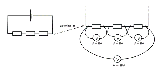
Let us look at this in a bit more detail. In figure 2 you can see what the different measurements for three identical resistors in series could look like. The total voltage across all three resistors is the sum of the voltages across the individual resistors. Resistors in series are known as voltage dividers because the total voltage across all the resistors is divided amongst the individual resistors.
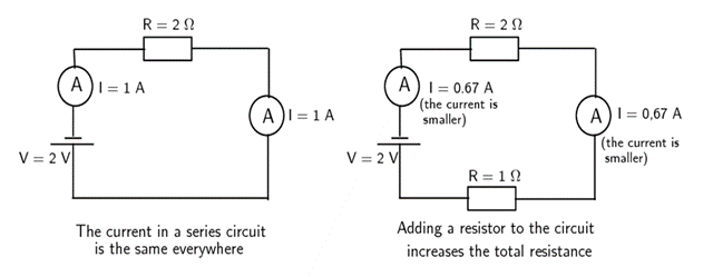
Consider the diagram in figure 3 below. On the left there is a circuit with a single resistor and a battery. No matter where we measure the current, it is the same in a series circuit. On the right, we have added a second resistor in series to the circuit. The total resistance of the circuit has increased, and you can see from the reading on the ammeter that the current in the circuit has decreased.
Example 2.1
A circuit contains two resistors in series. The resistors have resistance values of [latex]\scriptsize 5\text{ }\Omega[/latex] and [latex]\scriptsize 17\text{ }\Omega[/latex].

What is the equivalent resistance in the circuit?
Solution
Step 1: Analyse the question
We are told that the circuit is a series circuit and that we need to calculate the equivalent resistance. The values of the two resistors have been given in the correct units, Ω.
Step 2: Apply the relevant principles
The equivalent resistance for resistors in series is the sum of the individual resistances. We can use:
[latex]\scriptsize {{R}_{s}}={{r}_{1}}+{{r}_{2}}...[/latex]
We have only two resistors:
[latex]\scriptsize {{R}_{s}}=5+17[/latex]
The equivalent resistance of the resistors in series is [latex]\scriptsize 22\text{ }\Omega[/latex].
Working with resistors in parallel
When we add resistors in parallel to a circuit:
- There are more paths for current to flow which ensures that the current splits across the different paths.
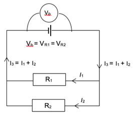
- The voltage is the same across the resistors. The voltage across the battery in the circuit is equal to the voltage across each of the parallel resistors:
[latex]\scriptsize {{V}_{{battery}}}={{V}_{1}}={{V}_{2}}={{V}_{3}}[/latex] - The resistance to the flow of current decreases. The equivalent resistance, [latex]\scriptsize {{R}_{p}}[/latex], is given by:
[latex]\scriptsize \displaystyle \frac{1}{{{{R}_{p}}}}=\displaystyle \frac{1}{{{{r}_{1}}}}+\displaystyle \frac{1}{{{{r}_{2}}}}...[/latex]
In contrast to series, when we add resistors in parallel, we create more paths along which current can flow. By doing this we decrease the total resistance of the circuit.
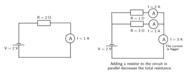
Look at the diagrams in figure 4. The ammeter shows a current of [latex]\scriptsize 1\text{ A}[/latex]. On the right we have added a second resistor in parallel to the first resistor. This has increased the number of paths (branches) the charge can take through the circuit – the total resistance has decreased. You can see that the current in the circuit has increased. Also notice that the current in the different branches can be different.
The equivalent resistance of a number of parallel resistors is NOT the sum of the individual resistances as the overall resistance decreases with more paths for the current. The equivalent resistance for parallel resistors is given by:
[latex]\scriptsize \displaystyle \frac{1}{{{{R}_{p}}}}=\displaystyle \frac{1}{{{{r}_{1}}}}+\displaystyle \frac{1}{{{{r}_{2}}}}...[/latex]
Example 2.2
A circuit contains two resistors in parallel. The resistors have resistance values of [latex]\scriptsize 15\text{ }\Omega \text{ }[/latex] and [latex]\scriptsize 7\text{ }\Omega[/latex].

What is the equivalent resistance in the circuit?
Solution
Step 1: Analyse the question
We are told that the resistors in the circuit are in parallel circuit and that we need to calculate the equivalent resistance. The values of the two resistors have been given in the correct units, Ω.
Step 2: Apply the relevant principles
The equivalent resistance for resistors in parallel is given by the formula:
[latex]\scriptsize \displaystyle \frac{1}{{{{R}_{p}}}}=\displaystyle \frac{1}{{{{r}_{1}}}}+\displaystyle \frac{1}{{{{r}_{2}}}}...[/latex]
We have only two resistors:
[latex]\scriptsize \begin{align*}\displaystyle \frac{1}{{{{R}_{p}}}}&=\displaystyle \frac{1}{{15}}+\displaystyle \frac{1}{7}\\{{R}_{p}}&=4.77\text{ }\Omega \end{align*}[/latex]
When solving for [latex]\scriptsize {{R}_{p}}[/latex], do not forget to invert.
Step 3: Quote the final result
The equivalent resistance of the resistors in parallel is [latex]\scriptsize 4.77\text{ }\Omega[/latex].
When two resistors are connected in parallel, their equivalent resistance is less than the value of the smallest resistor in the combination on its own. This is because the parallel connection opens more pathways for the current to move through, so there is less total resistance to the flow of the current.
When current enters a parallel branch in a circuit, it is divided. The branch with the lower resistance receives a higher current. For this reason, parallel resistors are called current dividers.
The potential difference across parallel branches is equal, even if the branches have different resistances. When parallel branches are connected directly across the battery, the potential difference across each branch is equal to the potential difference of the battery.
Exercise 2.1
- The battery in the circuit has a potential difference of [latex]\scriptsize 8\text{ V}[/latex].
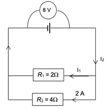
- Find the unknown currents I1 and I2
- Find the potential difference across the [latex]\scriptsize 4\text{ }\Omega[/latex] and [latex]\scriptsize 2\text{ }\Omega[/latex] resistors.
- .
- Calculate the total resistance in the circuit below:
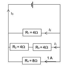
- Find currents I1 , I2 and I3.
- The terminal potential difference of the battery is [latex]\scriptsize 8\text{ V}\text{. }[/latex]Find the potential difference across resistors [latex]\scriptsize {{\text{R}}_{1}},\text{ }{{\text{R}}_{2}}\text{ and }{{\text{R}}_{4}}[/latex].
- If the branch with the resistor [latex]\scriptsize {{\text{R}}_{4}}[/latex] is removed from the circuit, explain what effect this will have on:
- The total resistance in the circuit.
- The current through the battery.
- The potential difference across resistor R1.
- Calculate the total resistance in the circuit below:
The full solutions are at the end of the unit.
Internal resistance
Up until now we have been dealing with ideal batteries in that they are not affected by the circuit or current in any way and provide a precise voltage until they go flat. In reality, the voltage of a battery will be affected when it is connected into a circuit.
If you measure the potential difference across the terminals of a battery not connected in a circuit, you will get a different value to what you measure when it is connected in a complete circuit. The value will be less when the battery is included in a complete circuit. The difference between these two readings is called the . Nothing has actually been lost but some energy carried by the charges has been transferred.
Real batteries are made from materials which have resistance. This means that real batteries are not just sources of potential difference (voltage), but they also possess what we call . As the charges flow through the battery, they will transfer some of their energy ‘pushing’ through this resistance. The energy per charge (voltage) when they come out of the battery will therefore be slightly less than the emf.
The internal resistance of a battery or cell is represented using the symbol [latex]\scriptsize r[/latex]. The internal resistance will be in series with the other resistors in the circuit which are referred to as the .

In the circuit above Ɛ represents the emf of the cell and [latex]\scriptsize V[/latex] is the voltage when the circuit is connected. The value of [latex]\scriptsize V[/latex] will be slightly less than the value of Ɛ, because of the internal resistance of the cell.
Summary
- Resistors can be arranged in series or parallel in electric circuits.
- When resistors are added in series:
- the equivalent resistance is calculated using the formula: [latex]\scriptsize {{R}_{s}}={{r}_{1}}+{{r}_{2}}...[/latex]
- the voltage of the battery is divided between them: [latex]\scriptsize {{V}_{{battery}}}={{V}_{1}}+{{V}_{2}}......[/latex]
- and the current is the same through all the resistors. [latex]\scriptsize {{I}_{{battery}}}={{I}_{{R1}}}={{I}_{{R2}}}...[/latex].
- When resistors are added in parallel:
- the equivalent resistance is calculated using the formula: [latex]\scriptsize \displaystyle \frac{1}{{{{R}_{p}}}}=\displaystyle \frac{1}{{{{r}_{1}}}}+\displaystyle \frac{1}{{{{r}_{2}}}}...[/latex]
- the voltage is the same across all the resistors: [latex]\scriptsize {{V}_{{battery}}}={{V}_{1}}={{V}_{2}}={{V}_{3}}[/latex]
- and the current is divided between them: [latex]\scriptsize {{I}_{{battery}}}={{I}_{{R1}}}+{{I}_{{R2}}}......[/latex].
- All cells or batteries have internal resistance. This is the energy used per unit charge when current passes through the battery itself.
Unit 2: Assessment
Suggested time to complete: 20 minutes
- Explain what happens when resistors are added in:
- series
- parallel
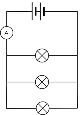
- Draw a circuit diagram which consists of the following components:
two cells in series, three light bulbs in parallel, and an ammeter measuring the total current in the circuit. - If you have a circuit consisting of four resistors of equal resistance in series and the total voltage across all of them is [latex]\scriptsize 17\text{ V}[/latex], what is the voltage across each of them?
- If you have a circuit consisting of four resistors of equal resistance in parallel and the total voltage across all of them is [latex]\scriptsize 17\text{ V}[/latex], what is the voltage across each of them?
- Calculate the equivalent resistance for the following circuit:
- .
- Calculate the equivalent resistance for the following circuits.
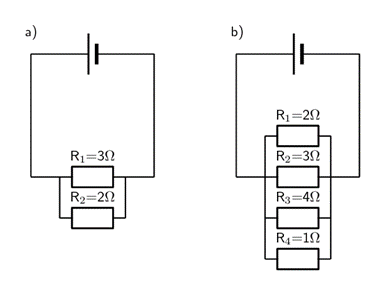
- .
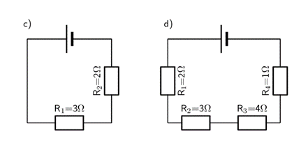
- Calculate the equivalent resistance for the following circuits.
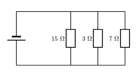
- There are three resistors in parallel with resistances of [latex]\scriptsize 3\text{ }\Omega[/latex], [latex]\scriptsize 4\text{ }\Omega[/latex] and[latex]\scriptsize 11\text{ }\Omega[/latex] What is the equivalent resistance of the parallel combination?
- The same three resistors as in question 6 are now arranged in series. What is the equivalent resistance of the series combination?
- The equivalent resistance of two resistors in parallel is [latex]\scriptsize 3\text{ }\Omega[/latex], the one resistor has a resistance of [latex]\scriptsize 5\text{ }\Omega[/latex], what is the resistance of the other resistor?
The full solutions are at the end of the unit.
Unit 2: Solutions
Exercise 2.1
- .
- [latex]\scriptsize {{R}_{1}}[/latex] has half the resistance of [latex]\scriptsize {{R}_{2}}[/latex], so the current divides so that the [latex]\scriptsize {{R}_{1}}[/latex] branch will receive double the current of the [latex]\scriptsize {{R}_{2}}[/latex] branch. Therefore:
[latex]\scriptsize \begin{align*}{{I}_{1}}&=2\text{ x 2 }\\&=\text{4 A}\end{align*}[/latex] [latex]\scriptsize \begin{align*}{{I}_{2}}&={{I}_{1}}+2\\&=4\text{ + 2 }\\&=\text{6 A}\end{align*}[/latex] - The potential difference across each of the parallel branches is equal to the potential difference across the battery.
Therefore [latex]\scriptsize {{V}_{{6\text{ }\Omega }}}={{V}_{{4\text{ }\Omega }}}={{V}_{{battery}}}=8\text{ V}[/latex]
- [latex]\scriptsize {{R}_{1}}[/latex] has half the resistance of [latex]\scriptsize {{R}_{2}}[/latex], so the current divides so that the [latex]\scriptsize {{R}_{1}}[/latex] branch will receive double the current of the [latex]\scriptsize {{R}_{2}}[/latex] branch. Therefore:
- .
- [latex]\scriptsize {{R}_{2}}[/latex] and [latex]\scriptsize {{R}_{3}}[/latex] are in series: [latex]\scriptsize {{R}_{s}}={{r}_{1}}+{{r}_{2}}=4+4=8\text{ }\Omega[/latex]
Now add the resistors in parallel:
[latex]\scriptsize \begin{align*}\displaystyle \frac{1}{{{{R}_{p}}}}&=\displaystyle \frac{1}{{{{r}_{1}}}}+\displaystyle \frac{1}{{{{r}_{2}}+{{r}_{3}}}}+\displaystyle \frac{1}{{{{r}_{4}}}}\\&=\displaystyle \frac{1}{4}+\displaystyle \frac{1}{8}+\displaystyle \frac{1}{8}\\&=\displaystyle \frac{2}{8}+\displaystyle \frac{1}{8}+\displaystyle \frac{1}{8}\\&=\displaystyle \frac{4}{8}\\{{R}_{p}}&=\displaystyle \frac{8}{4}\\&=2\text{ }\Omega \end{align*}[/latex] - The branch with [latex]\scriptsize {{R}_{2}}[/latex] and [latex]\scriptsize {{R}_{3}}[/latex] has the same resistance as [latex]\scriptsize {{R}_{4}}[/latex], so this branch will receive the same current as the [latex]\scriptsize {{R}_{4}}[/latex] branch. So [latex]\scriptsize {{I}_{1}}=1\text{ A}[/latex].
[latex]\scriptsize {{R}_{1}}[/latex] has half the resistance of [latex]\scriptsize {{R}_{4}}[/latex], so the current divides so that the [latex]\scriptsize {{R}_{1}}[/latex] branch will receive double the current of the [latex]\scriptsize {{R}_{4}}[/latex] branch. So [latex]\scriptsize {{I}_{2}}=2\text{ A}[/latex].
[latex]\scriptsize {{I}_{3}}={{I}_{1}}+{{I}_{2}}+1\text{ A = 2+1+1= 4 A}[/latex] - [latex]\scriptsize {{V}_{{R1}}}=8\text{ V}[/latex] since it is connected directly across the battery, so it will have the same voltage as the battery.
[latex]\scriptsize {{V}_{{R2}}}=4\text{ V}[/latex] since this branch has two [latex]\scriptsize 4\text{ }\Omega \text{ }[/latex] resistors that are together connected across the battery, so they share [latex]\scriptsize 8\text{ V }[/latex]equally between them.
[latex]\scriptsize {{V}_{{R4}}}=8\text{ V}[/latex] since it is connected directly across the battery. - .
- If one of the parallel branches is removed, then there are fewer pathways for the current, so the total resistance will be increased.
- Since the resistance is increased, the current through the battery will decrease because current is inversely proportional to resistance.
- The potential difference across resistor [latex]\scriptsize {{\text{R}}_{1}}[/latex] will not change, because it is connected directly across the battery, so will receive the full battery terminal potential difference.
- [latex]\scriptsize {{R}_{2}}[/latex] and [latex]\scriptsize {{R}_{3}}[/latex] are in series: [latex]\scriptsize {{R}_{s}}={{r}_{1}}+{{r}_{2}}=4+4=8\text{ }\Omega[/latex]
Unit 2: Assessment
- .
- The equivalent resistance of the circuit will increase.
- The equivalent resistance of the circuit will decrease.
- .
- Resistors in series will share the voltage provided by the battery. As the resistors are identical, they will share the voltage equally.
[latex]\scriptsize \displaystyle \frac{{17}}{4}=4.25\text{ V}[/latex] They will each get [latex]\scriptsize 4.25\text{ V}[/latex]. - Resistors in parallel each get the same voltage as the battery. Therefore they will each get [latex]\scriptsize 17\text{ V}[/latex].
- .
[latex]\scriptsize \begin{align*}\displaystyle \frac{1}{{{{R}_{p}}}}&=\displaystyle \frac{1}{{{{r}_{1}}}}+\displaystyle \frac{1}{{{{r}_{2}}}}+\displaystyle \frac{1}{{{{r}_{3}}}}\\&=\displaystyle \frac{1}{{15}}+\displaystyle \frac{1}{3}+\displaystyle \frac{1}{7}\\{{R}_{p}}&=\text{ 1}\text{.84 }\Omega \end{align*}[/latex] - .
- .
[latex]\scriptsize \begin{align*}\displaystyle \frac{1}{{{{R}_{p}}}}&=\displaystyle \frac{1}{{{{r}_{1}}}}+\displaystyle \frac{1}{{{{r}_{2}}}}\\&=\displaystyle \frac{1}{3}+\displaystyle \frac{1}{2}\\\text{ }{{R}_{p}}&=\text{ 1}\text{.2 }\Omega \end{align*}[/latex] - .
[latex]\scriptsize \begin{align*}\displaystyle \frac{1}{{{{R}_{p}}}}&=\displaystyle \frac{1}{{{{r}_{1}}}}+\displaystyle \frac{1}{{{{r}_{2}}}}+\displaystyle \frac{1}{{{{r}_{3}}}}+\displaystyle \frac{1}{{{{r}_{4}}}}\\&=\displaystyle \frac{1}{2}+\displaystyle \frac{1}{3}+\displaystyle \frac{1}{4}+\displaystyle \frac{1}{1}\\{{R}_{p}}&=\text{ 0}\text{.48 }\Omega \end{align*}[/latex] - .
[latex]\scriptsize \begin{align*}{{R}_{s}}&={{r}_{1}}+{{r}_{2}}\\&=\text{3 + 2 }\\&=\text{5 }\Omega \end{align*}[/latex] - .
[latex]\scriptsize \begin{align*}{{R}_{s}}&={{r}_{1}}+{{r}_{2}}+{{r}_{3}}+{{r}_{4}}\\&=\text{2 + 3 + 4 + 1 }\\&=\text{10 }\Omega \end{align*}[/latex]
- .
- .
[latex]\scriptsize \begin{align*}\displaystyle \frac{1}{{{{R}_{p}}}}&=\displaystyle \frac{1}{{{{r}_{1}}}}+\displaystyle \frac{1}{{{{r}_{2}}}}+\displaystyle \frac{1}{{{{r}_{3}}}}\\&=\displaystyle \frac{1}{3}+\displaystyle \frac{1}{4}+\displaystyle \frac{1}{{11}}\\{{R}_{p}}&=\text{ 1}\text{.48 }\Omega \end{align*}[/latex] - .
[latex]\scriptsize \begin{align*}{{R}_{s}}&={{r}_{1}}+{{r}_{2}}+{{r}_{3}}\\&=\text{3 + 4 + 11 }\\&=\text{18 }\Omega \end{align*}[/latex] - .
[latex]\scriptsize \begin{align*}\displaystyle \frac{1}{{{{R}_{p}}}}&=\displaystyle \frac{1}{{{{r}_{1}}}}+\displaystyle \frac{1}{{{{r}_{2}}}}\\\displaystyle \frac{1}{3}&=\displaystyle \frac{1}{5}+\displaystyle \frac{1}{{{{r}_{2}}}}\\\displaystyle \frac{1}{{{{r}_{2}}}}&=\displaystyle \frac{1}{3}-\displaystyle \frac{1}{5}\\\text{ }{{\text{r}}_{2}}&=\text{ 7}\text{.5 }\Omega \end{align*}[/latex]
Media Attributions
- img01_Table 1_1 © DHET is licensed under a CC BY (Attribution) license
- img01_Table 1_2 © DHET is licensed under a CC BY (Attribution) license
- img01_Table 1_3 © DHET is licensed under a CC BY (Attribution) license
- img01_Table 1_3 © DHET is licensed under a CC BY (Attribution) license
- img01_Table 1_4 © DHET is licensed under a CC BY (Attribution) license
- img01_Table 1_5 © DHET is licensed under a CC BY (Attribution) license
- img01_Table 1_6a © DHET is licensed under a CC BY (Attribution) license
- img01_Table 1_6b © DHET is licensed under a CC BY (Attribution) license
- img01_Table 1_6c © DHET is licensed under a CC BY (Attribution) license
- img01_Table 1_6d © DHET is licensed under a CC BY (Attribution) license
- img01_Table 1_7 © DHET is licensed under a CC BY (Attribution) license
- img01_Table 1_8 © DHET is licensed under a CC BY (Attribution) license
- img01_Table 1_9 © DHET is licensed under a CC BY (Attribution) license
- img01_Table 1_10 © DHET is licensed under a CC BY (Attribution) license
- img01_Table 1_11 © DHET is licensed under a CC BY (Attribution) license
- img01_Table 1_12 © DHET is licensed under a CC BY (Attribution) license
- img02_Figure1 © Siyavula is licensed under a CC BY-NC-ND (Attribution NonCommercial NoDerivatives) license
- img03_Figure2 © Siyavula is licensed under a CC BY-NC-ND (Attribution NonCommercial NoDerivatives) license
- img04_Figure3 © Siyavula is licensed under a CC BY-NC-ND (Attribution NonCommercial NoDerivatives) license
- img05_Example2.1 © Siyavula is licensed under a CC BY-NC-ND (Attribution NonCommercial NoDerivatives) license
- img06_Figure4 © Siyavula is licensed under a CC BY-NC-ND (Attribution NonCommercial NoDerivatives) license
- img07_Example2.2 © Siyavula is licensed under a CC BY-NC-ND (Attribution NonCommercial NoDerivatives) license
- img08_Figure5 © DHET is licensed under a CC BY (Attribution) license
- img09_Ex2.1Q1 © DHET is licensed under a CC BY (Attribution) license
- img10_Ex2.1Q3 © DHET is licensed under a CC BY (Attribution) license
- img11_Figure6 © Siyavula is licensed under a CC BY-NC-ND (Attribution NonCommercial NoDerivatives) license
- img12_AssessmentQ5 © Siyavula is licensed under a CC BY-NC-ND (Attribution NonCommercial NoDerivatives) license
- img13_AssessmentQ6 © Siyavula is licensed under a CC BY-NC-ND (Attribution NonCommercial NoDerivatives) license
- img13_AssessmentQ6 © Siyavula is licensed under a CC BY-NC-ND (Attribution NonCommercial NoDerivatives) license
- img14_AssessmentQ2answer © Siyavula is licensed under a CC BY-NC-ND (Attribution NonCommercial NoDerivatives) license
the combined resistance of all resistors in a circuit
the energy used per unit of charge to drive charge through the battery (the difference between the emf and the voltage reading)
the resistance of the battery
the combined resistance of all the resistors in the circuit excluding the internal resistance of the battery
