Magnetism and electricity: State, analyse and apply principles of static electricity (electrostatics)
Unit 3: Electric potential and capacitance
Leigh Kleynhans
Unit outcomes
By the end of this unit you will be able to:
- Define and apply electric potential energy and electric potential.
- Define capacitance.
- Apply the principle of capacitance to the parallel plate capacitor.
- Identify and apply the relation between charge, potential difference, and capacitance.
- Describe, identify, and apply the capacitor as a circuit device.
What you should know
Before you start this unit, make sure you can:
- Draw and identify the electric field between oppositely charged, parallel plates. You can refer to level 3, subject outcome 4.1, unit 2 to revise this.
- Use the two formulae to calculate the electric field strength between parallel plates. You can refer to level 3, subject outcome 4.1, unit 2 to revise this.
Introduction
In this unit we will look at how charges can gain electric potential energy and how this can create an electric potential difference. This concept is used in circuit components called capacitors, and we will discover how they work.
Electric potential energy
Potential energy is a ‘stored’ energy that an object has by virtue of its position. You already know from level 2, subject outcome 2.3, unit 1 that the higher above the surface of the earth, the greater an object’s gravitational potential energy.
The same principle can be applied to charges in an electric field. Consider the diagram in Figure 1 below. The positive test charge will have a high when it is nearer the positively charged plate, and as it moves towards the negative plate its electric potential energy will decrease. Think of a mass being dropped – it has high gravitational potential energy at its maximum height and decreasing gravitational potential energy the closer it gets to the ground.
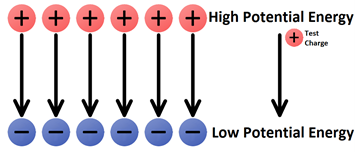
Moving a positive test charge against the direction of an electric field is like moving a mass upward within Earth’s gravitational field. Both movements would be like ‘going against nature’ and would require work by an external force. This work would in turn increase the potential energy of the mass or charge. On the other hand, the movement of a positive test charge in the direction of an electric field would be like a mass falling downward within Earth’s gravitational field. Both movements would be like ‘going with nature’ and would occur without the need of work by an external force. This motion would result in the loss of potential energy. Electric potential energy is the stored energy related to the location of the charge within an electric field. The positive test charge will have a different electric potential energy at various locations within an electric field.
Work would be required to move a positive test charge towards the positive plate, against the electric field. The amount of force involved in doing the work is dependent upon the amount of charge being moved. The greater the charge on the test charge, the greater the repulsive force and the more work that would have to be done on it to move it the same distance. If two objects of different charge – with one being twice the charge of the other – are moved the same distance into the electric field, then the object with twice the charge would require twice the force and thus twice the amount of work. This work would change the electric potential energy by an amount that is equal to the amount of work done. Thus, the electric potential energy is dependent upon the amount of charge on the object experiencing the field and upon the location within the field. (Just as gravitational potential energy at a point is dependent on both the mass and the height of the object.)
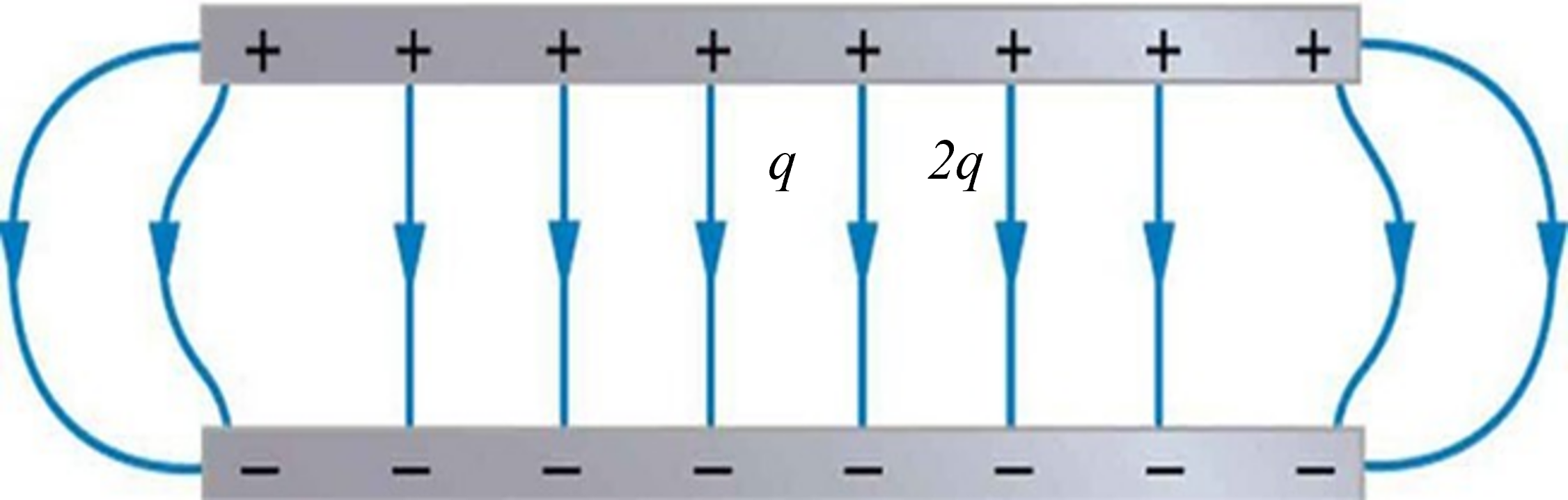
The charge [latex]\scriptsize 2q[/latex] will have twice the electric potential energy as charge [latex]\scriptsize q[/latex].
Electric potential
While electric potential energy has a dependency upon the charge of the object experiencing the electric field, is purely location dependent. Electric potential is the potential energy per unit charge.
[latex]\scriptsize \text{Electric potential = }\displaystyle \frac{{\text{potential energy (measured in Joules)}}}{{\text{charge (measured in coulombs)}}}[/latex]
A test charge with twice the quantity of charge would possess twice the electric potential energy at a given location; yet its electric potential at that location would be the same as any other test charge. Electric potential is simply a property of the location within an electric field. Suppose that the electric potential at a given location is [latex]\scriptsize 12[/latex] joules per coulomb, then that is the electric potential of a [latex]\scriptsize 1[/latex] coulomb or a [latex]\scriptsize 2[/latex] coulomb charged object. Stating that the electric potential at a given location is [latex]\scriptsize 12[/latex] joules per coulomb, would mean that a [latex]\scriptsize 2[/latex] coulomb object would possess [latex]\scriptsize 24[/latex] joules of potential energy at that location and a [latex]\scriptsize 0.5[/latex] coulomb object would experience [latex]\scriptsize 6[/latex] joules of potential energy at the location.
Consider the positive charge in an electric field in the diagram in Figure 3:

In moving the charge against the electric field from location A to location B, work will have to be done on the charge by an external force. The work done on the charge changes its potential energy to a higher value; and the amount of work that is done is equal to the change in the potential energy. As a result of this change in electric potential energy, there is also a difference in electric potential between locations A and B. This difference in electric potential is represented by the symbol [latex]\scriptsize \Delta V[/latex] and is formally referred to as the . By definition, the electric potential difference is the difference in electric potential ([latex]\scriptsize V[/latex]) between the final and the initial location when work is done upon a charge to change its electric potential energy. In equation form, the electric potential difference is:
[latex]\scriptsize \Delta V={{V}_{B}}-{{V}_{A}}=\displaystyle \frac{{\text{Work}}}{{\text{Charge}}}=\displaystyle \frac{{\text{Change in potential energy}}}{{\text{Charge}}}[/latex]
The standard metric unit for electric potential difference is the , abbreviated V. One volt is equivalent to one joule per coulomb. If the electric potential difference between two locations is [latex]\scriptsize 1[/latex] volt, then one coulomb of charge will gain [latex]\scriptsize 1[/latex] joule of potential energy when moved between those two locations. If the electric potential difference between two locations is [latex]\scriptsize 3[/latex] volts, then one coulomb of charge will gain [latex]\scriptsize 3[/latex] joules of potential energy when moved between those two locations. And finally, if the electric potential difference between two locations is [latex]\scriptsize 12[/latex] volts, then one coulomb of charge will gain [latex]\scriptsize 12[/latex] joules of potential energy when moved between those two locations. Because electric potential difference is expressed in units of volts, it is sometimes referred to as the .
Exercise 3.1
- The quantity electric potential is defined as the amount of _____.
- electric potential energy
- force acting upon a charge
- potential energy per charge
- force per charge
- Complete the following statement:
.
When work is done on a positive test charge by an external force to move it from one location to another, potential energy _________ (increases, decreases) and electric potential _________ (increases, decreases). - The following diagrams show an electric field (represented by arrows) and two points – labelled A and B – located within the electric field. A positive test charge is shown at point A. For each diagram, indicate whether work must be done upon the charge to move it from point A to point B. Finally, indicate the point (A or B) with the greatest electric potential energy and the greatest electric potential.
- .

- .

- .

- .

- .
The full solutions are at the end of the unit.
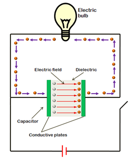
Capacitors
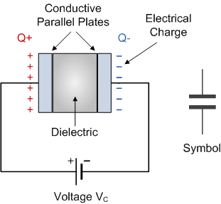
A is a circuit component consisting of two parallel plates which have the ability or ‘capacity’ to store energy in the form of an electrical charge producing a potential difference across its plates, much like a small rechargeable battery.
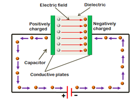
In its basic form, a capacitor consists of two or more parallel conductive (metal) plates which are not connected or touching each other but are electrically separated either by air or by some form of a good insulating material such as waxed paper or plastic, which is called the .
Charging a capacitor
When parallel plates are connected to a battery, the negative terminal supplies electrons and the positive terminal takes in electrons. In this way, one plate in Figure 4, becomes positively charged and the other plate becomes negatively charged. Eventually the build-up of charge prevents any further movement of electrons. During the charging process there is current in the wires connecting the plates to the battery which decreases until there is no more current flow. Once charged, the potential difference (P.D.) across the plates is the same as that of the battery.
The charge is now stored in the parallel plates (capacitor), even when the battery is disconnected and there is no more flow of current.
Discharging a capacitor
When a charged capacitor is connected in a circuit it will be able to release the electrical energy that has been stored in it. It acts like a battery and electrons will flow from the negative plate to the positive plate. As the capacitor discharges, the P.D. will decrease across it. The current will be at a maximum when the capacitor first starts to discharge and there will be no current flow once it has discharged completely.
The direction in which the current flows when a capacitor is discharged will be opposite to the current flow when it is being charged.
Capacitance
The property of a capacitor to store charge on its plates in the form of an electrostatic field is called the of the capacitor. The capacitance of a capacitor is determined by the surface area of the conductive plates and the distance of separation between them. Altering any two of these values alters the value of its capacitance. Because capacitors store the energy of the electrons in the form of an electrical charge on the plates, the larger the plates and/or smaller their separation the greater will be the charge that the capacitor holds for any given voltage across its plates. In other words, larger plates, smaller distance, more capacitance.
The capacitance of a capacitor can be calculated using the following formula:
[latex]\scriptsize C=\displaystyle \frac{Q}{V}[/latex]
Where:
[latex]\scriptsize Q[/latex] is the charge measured in coulombs ([latex]\scriptsize \text{C}[/latex])
[latex]\scriptsize V[/latex] is the voltage measured in volts ([latex]\scriptsize \text{V}[/latex])
[latex]\scriptsize C[/latex] is the capacitance measured in coulombs per volt ([latex]\scriptsize \text{C}\text{.}{{\text{V}}^{{-1}}}[/latex]) which is equivalent to
Take note!
The units milliFarads ([latex]\scriptsize \text{mF}[/latex]), microFarads ([latex]\scriptsize \mu \text{F}[/latex]), nanoFarads ([latex]\scriptsize \text{nF}[/latex]) and picoFarads ([latex]\scriptsize \text{pF}[/latex]) are often used in the section. They must be converted to Farads before substituting into an equation.
Conversion factors:
[latex]\scriptsize \begin{align*}1\text{ mF}&= \text{1 x 1}{{\text{0}}^{{-3}}}\text{ F}\\\text{1 }\mu \text{F}&= \text{1 x 1}{{\text{0}}^{{-6}}}\text{ F}\\\text{1 nF}&= \text{1 x 1}{{\text{0}}^{{-9}}}\text{ F}\\\text{1 pF}&= \text{1 x 1}{{\text{0}}^{{-12}}}\text{ F}\end{align*}[/latex]
Example 3.1
Calculate the capacitance of a capacitor if the charge stored on the plates is [latex]\scriptsize 3\text{ nC}[/latex] and the voltage is [latex]\scriptsize 0.6\text{ V}[/latex].
Solution
Step 1: Write down the given information, check units and convert if required
[latex]\scriptsize \begin{align*}Q&=3\text{ nC = 3 x 1}{{\text{0}}^{{-9}}}\text{ C}\\V&=0.6\text{ V}\end{align*}[/latex]
Step 2: Write down the formula
[latex]\scriptsize C=\displaystyle \frac{Q}{V}[/latex]
Step 3: Substitute the values and calculate the answer
[latex]\scriptsize \displaystyle \frac{{3\text{ x 1}{{\text{0}}^{{-9}}}}}{{0.6}}=5\text{ x 1}{{\text{0}}^{{-9}}}\text{ F}[/latex]
Uses of capacitors
Timing
Capacitors can be used in a time-dependant circuit because their charging and discharging takes place at regular intervals. This could be connected to any light-emitting diode (LED) or loudspeaker system, and it is likely that any flashing light that you see, or regular beeping uses a timing capacitor.
Smoothing
A capacitor can convert AC (alternating current) to DC (direct current) by ‘smoothing’ the current. Imagine AC current as a single line constantly snaking up and down. A capacitor will charge as this line rises and at the peak will discharge. Once fully discharged, it starts to charge again, so that the output current never has time to fully dip and operates as if it were direct current.
Coupling
Capacitors can let AC current pass yet block DC current in a process called coupling. This is used in the case of a loudspeaker. Speakers work by converting an alternating current into sound, but they could be damaged by any direct current that reaches them. A capacitor prevents this from happening.
Tuning
The charging and discharging current of a capacitor takes place at regular intervals, but it can be changed by altering the capacitor. If the frequency of these intervals is the same as the frequency of a nearby radio station, then the amplifier in the radio will strengthen this signal and you will hear the broadcast.
Storing energy
In some cases, like the flash circuit of a camera, you need a build-up of energy and then a sudden release. This is exactly what a capacitor does. In the camera circuit, you press the button to take the picture and a charge is released to the capacitor. Once it has reached the peak level, the capacitor discharges, causing a flash.
Note
You can watch this video to consolidate the concepts of capacitors and capacitance.
Summary
In this unit you have learnt the following:
- Charges gain electric potential energy when an external force moves them in an electric field. For example, a positive charge will have more potential energy the closer it moves towards the positive plate in the electric field between oppositely charged plates.
- The electric potential is the energy per unit charge.
- Electric potential difference is the difference between the electric potential between two points in an electric field.
- Capacitors are devices used in electrical circuits to store charge.
- Capacitance is the measure of the ability of a capacitor to store charge.
- Factors that affect the capacitance of a capacitor are the surface area of the plates and the distance between the plates.
- Capacitance can be calculated using the formula: [latex]\scriptsize C\text{ = }\displaystyle \frac{Q}{V}[/latex].
- The units in which capacitance is measured are Farads.
Unit 3: Assessment
Suggested time to complete: 20 minutes
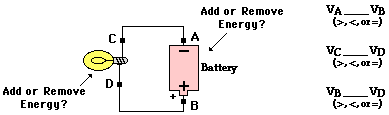
- The following circuit consists of a D-cell and a light bulb. Use >, <, and = symbols to compare the electric potential at A to B and at C to D. Indicate whether the devices add energy to or remove energy from the charge.
- Use your understanding of the mathematical relationship between work, potential energy, charge and electric potential difference to complete the following statements:
- A [latex]\scriptsize 9[/latex] volt battery will increase the potential energy of [latex]\scriptsize 1[/latex] coulomb of charge by ____ joules.
- A [latex]\scriptsize 9[/latex] volt battery will increase the potential energy of [latex]\scriptsize 2[/latex] coulombs of charge by ____ joules.
- A [latex]\scriptsize 9[/latex] volt battery will increase the potential energy of [latex]\scriptsize 0.5[/latex] coulombs of charge by ____ joules.
- A ___volt battery will increase the potential energy of [latex]\scriptsize 3[/latex] coulombs of charge by [latex]\scriptsize 18[/latex] joules.
- A ___volt battery will increase the potential energy of [latex]\scriptsize 2[/latex] coulombs of charge by [latex]\scriptsize 3[/latex] joules.
- A [latex]\scriptsize 1.5[/latex] volt battery will increase the potential energy of ____ coulombs of charge by [latex]\scriptsize 0.75[/latex] joules.
- A [latex]\scriptsize 12[/latex] volt battery will increase the potential energy of ____ coulombs of charge by [latex]\scriptsize 6[/latex] joules.
- What charge is stored in a [latex]\scriptsize 180\text{ }\mu \text{F}[/latex] capacitor when [latex]\scriptsize 120\text{ V}[/latex] is applied to it?
- Find the charge stored when [latex]\scriptsize 5.50\text{ V}[/latex] is applied to an [latex]\scriptsize 8.00\text{ pF}[/latex] capacitor.
- Calculate the voltage applied to a [latex]\scriptsize 2\text{ }\mu \text{F}[/latex] capacitor when it holds [latex]\scriptsize 3.1\text{ mC}[/latex] of charge.
- What voltage must be applied to an [latex]\scriptsize 8.00\text{ nF}[/latex] capacitor to store [latex]\scriptsize 0.160\text{ mC}[/latex] of charge?
- What capacitance is needed to store [latex]\scriptsize 3.00\text{ }\mu \text{C}[/latex] of charge at a voltage of [latex]\scriptsize 120\text{ V}[/latex]?
- Name three devices that make use of capacitors in their electrical circuits.
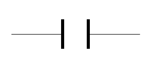
- Draw the symbol used for a capacitor in a circuit.
The full solutions are at the end of the unit.
Unit 3: Solutions
Exercise 3.1
- Answer: C (Electric potential is the amount of potential energy per unit of charge.)
- When work is done on a positive test charge to move it from one location to another, potential energy increases and electric potential increases.
- .
- .
.
Work done on charge? No (The + charge is moving with nature; work is not required when it moves with the E field.)
.
Electric PE is greatest at: A (When a + charge moves naturally in the direction of the E field, it is moving from high PE to low PE. So the charge has a higher PE at A.)
.
Electric potential is greatest at: A (For the same charge, the electric potential is greatest at locations of higher potential energy.) - .
.
Work done on charge? Yes (The + charge is moving against nature; work is required to move it against the E field.)
.
Electric PE is greatest at: B (When work is done to move an object against nature, the PE of the object increases. So the charge possesses more PE when at B.)
.
Electric potential is greatest at: B (For the same charge, the electric potential is greatest at locations of higher potential energy.) - .
Work done on charge? No (The + charge is moving with nature; work is not required when it moves with the E field.)
.
Electric PE is greatest at: A (When a + charge moves naturally in the direction of the E field, it is moving from high PE to low PE. So the charge has a higher PE at A.)
.
Electric potential is greatest at: A (For the same charge, the electric potential is greatest at locations of higher potential energy.) - .
.
Work done on charge? Yes (The + charge is moving against nature; work is required to move it against the E field.)
.
Electric PE is greatest at: B (When work is done to move an object against nature, the PE of the object increases. So the charge possesses more PE when at B.)
.
Electric potential is greatest at: B (For the same charge, the electric potential is greatest at locations of higher potential energy.)
- .
Unit 3: Assessment
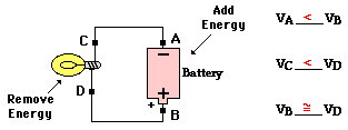
- The cell adds energy to the charge to move it from the low potential, negative terminal to the high potential, positive terminal. The light bulb removes energy from the charge. Thus, the charge is at lower energy and a lower electric potential when at locations C and A. Since there is no energy-consuming circuit element between locations B and D, these two locations have roughly the same electric potential. The same can be said of locations C and A.
- This question targets your mathematical understanding of the relationship between the electrical potential difference, the voltage and the amount of charge. The relationship is expressed by the following equation:
.
[latex]\scriptsize \Delta V={{V}_{B}}-{{V}_{A}}=\displaystyle \frac{{\text{Work}}}{{\text{Charge}}}=\displaystyle \frac{{\text{Change in potential energy}}}{{\text{Charge}}}[/latex]- A [latex]\scriptsize 9[/latex] volt battery will increase the potential energy of [latex]\scriptsize 1[/latex] coulomb of charge y [latex]\scriptsize 9[/latex] joules.
- A [latex]\scriptsize 9[/latex] volt battery will increase the potential energy of [latex]\scriptsize 2[/latex] coulombs of charge by [latex]\scriptsize 18[/latex] joules.
- A [latex]\scriptsize 9[/latex] volt battery will increase the potential energy of [latex]\scriptsize 0.5[/latex] coulombs of charge by [latex]\scriptsize 4.5[/latex] joules.
- A [latex]\scriptsize 6[/latex] volt battery will increase the potential energy of [latex]\scriptsize 3[/latex] coulombs of charge by [latex]\scriptsize 18[/latex] joules.
- A [latex]\scriptsize 1.5[/latex] volt battery will increase the potential energy of [latex]\scriptsize 2[/latex] coulombs of charge by [latex]\scriptsize 3[/latex] joules.
- A [latex]\scriptsize 1.5[/latex] volt battery will increase the potential energy of [latex]\scriptsize 0.5[/latex] coulombs of charge by [latex]\scriptsize 0.75[/latex] joules.
- A [latex]\scriptsize 12[/latex] volt battery will increase the potential energy of [latex]\scriptsize 0.5[/latex] coulombs of charge by [latex]\scriptsize 6[/latex] joules.
- .
[latex]\scriptsize \begin{align*}C&=\text{180 }\mu \text{F = 180 x 1}{{\text{0}}^{{-6}}}\text{ F}\\V&=\text{120 V}\\Q&=\text{?}\\C&=\displaystyle \frac{Q}{V}\\180\text{ x 1}{{\text{0}}^{{-6}}}&=\text{ }\displaystyle \frac{Q}{{120}}\\Q&=0.022\text{ C}\end{align*}[/latex] - .
[latex]\scriptsize \displaystyle \begin{align*}C&=\text{8}\text{.00 pF = 8 x 1}{{\text{0}}^{{-12}}}\text{ F}\\V&=\text{5}\text{.50 V}\\Q&=\text{?}\\C&=\displaystyle \frac{Q}{V}\\8\text{ x 1}{{\text{0}}^{{-12}}}&=\text{ }\displaystyle \frac{Q}{{5.50}}\\Q&=4.4\text{ x1}{{\text{0}}^{{-11}}}\text{ C}\end{align*}[/latex] - .
[latex]\scriptsize \begin{align*}C&=\text{2 }\mu \text{F = 2 x 1}{{\text{0}}^{{-6}}}\text{ F}\\Q&=\text{3}\text{.1 mC = 3}\text{.1 x 1}{{\text{0}}^{{-3}}}\text{ C}\\V&=\text{?}\\C&=\displaystyle \frac{Q}{V}\\\text{2 x 1}{{\text{0}}^{{-6}}}&=\text{ }\displaystyle \frac{{3.1\text{ x 1}{{\text{0}}^{{-3}}}}}{V}\\V&=\text{ 1 550 V}\end{align*}[/latex] - .
[latex]\scriptsize \begin{align*}C&=\text{8}\text{.00 nF = 8 x 1}{{\text{0}}^{{-9}}}\text{ F}\\Q&=\text{0}\text{.16 mC = 0}\text{.16 x 1}{{\text{0}}^{{-3}}}\text{ C}\\V&=\text{?}\\C&=\displaystyle \frac{Q}{V}\\\text{8 x 1}{{\text{0}}^{{-9}}}&=\text{ }\displaystyle \frac{{\text{0}\text{.16 x 1}{{\text{0}}^{{-3}}}}}{V}\\V&=\text{ 20 000 V}\end{align*}[/latex] - .
[latex]\scriptsize \begin{align*}Q&=\text{3}\text{.00 }\mu \text{C = 3 x 1}{{\text{0}}^{{-6}}}\text{ C}\\V&=\text{120 V}\\\text{Q}&= \text{?}\\C&=\displaystyle \frac{Q}{V}\text{ = }\displaystyle \frac{{3\text{ x 1}{{\text{0}}^{{-6}}}}}{{120}}\text{ = 2}\text{.5 x 1}{{\text{0}}^{{-8}}}\text{ F}\\\end{align*}[/latex] - Capacitors are used loudspeakers, camera flashed, radios, flashing lights, beeping of an alarm system.
- .
Media Attributions
- img01_Figure1 © L Kleynhans is licensed under a CC BY (Attribution) license
- img02_Figure2 © L Kleynhans is licensed under a CC BY (Attribution) license
- img03_Figure3 © L Kleynhans is licensed under a CC BY (Attribution) license
- img09_Ex3.1Q3a)answer © DHET is licensed under a CC BY (Attribution) license
- img10_Ex3.1Q3b)answer © DHET is licensed under a CC BY (Attribution) license
- img11_Ex3.1Q3c)answer © DHET is licensed under a CC BY (Attribution) license
- img12_Ex3.1Q3d)answer © DHET is licensed under a CC BY (Attribution) license
- img05_Figure4 © L Kleynhans is licensed under a CC BY (Attribution) license
- img06_Figure5 © L Kleynhans is licensed under a CC BY (Attribution) license
- img07_Figure6 © L Kleynhans is licensed under a CC BY (Attribution) license
- img08AssessmentQ1 © L Kleynhans is licensed under a CC BY (Attribution) license
- img13_AssessmentQ1answer © L Kleynhans is licensed under a CC BY (Attribution) license
- img14_AssessmentQ9answer © DHET is licensed under a CC BY (Attribution) license
the stored energy that a charge possesses which is determined by the amount of charge and the position in an electric field
the amount of potential energy per unit charge
the difference in electric potential between the final and the initial location when work is done on a charge to change its electric potential energy
the unit in which potential difference is measured
the amount of potential energy per unit charge
a circuit component consisting of two parallel plates that serves to store charge
the insulating material between the parallel plates of a capacitor that prevents the plates from touching each other
the ability of a capacitor to store charge, the amount of charge per volt, measured in Farads
the units in which capacitance is measured
