Mechanics: Describe, analyse and apply principles of non-concurrent forces
Unit 2: Force diagrams of non-parallel forces
Linda Pretorius
Unit outcomes
By the end of this unit you will be able to:
- Identify and draw a labelled force diagram of parallel forces to solve problems using the centre of gravity.
- Identify and draw a labelled force diagram of non-parallel forces to solve problems.
What you should know
Before you start this unit, make sure you can:
- Define non-concurrent forces. Refer to level 3 subject outcome 2.3 unit 1 if you need help with this.
- Define torque. Refer to level 3 subject outcome 2.3 unit 1 if you need help with this.
- State the two conditions for equilibrium. Refer to level 3 subject outcome 2.3 unit 1 if you need help with this.
- Resolve a force into components. Refer to level 3 subject outcome 2.2 unit 2 if you need help with this.
- Draw a force diagram. Refer to level 3 subject outcome 2.2 unit 2 if you need help with this.
Introduction
In this unit you will apply your knowledge of non-concurrent forces to solve practical problems. You will learn to work with both parallel and non-parallel non-concurrent forces and determine how to keep systems in equilibrium and stable.
Centre of gravity
A system that is balanced – in other words in equilibrium – is not necessarily stable. For a system to be balanced and stable, the must be directly over the pivot point. An object’s centre of gravity is the point through which its weight acts.
Consider the pencils in figure 1.
| A.
|
B.
|
C.
|
| Figure 1: Three pencils in various states of equilibrium | ||
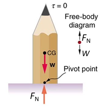
- In figure 1 A, the pencil is in stable equilibrium.
- The system is in equilibrium because the sum of the vertical forces (the weight, [latex]\scriptsize W[/latex], and the normal force, [latex]\scriptsize {{F}_{\text{N}}}[/latex]) are balanced and the sum of the torques is also zero. Both conditions for equilibrium are therefore met.
- The system is stable, because the weight acts directly over the pivot point. In other words, the centre of gravity is directly over the pivot point
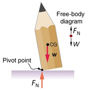
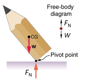
- In figure 1 B and C, respectively, the pencil experiences an unstable equilibrium.
- Although the vertical forces (the weight, [latex]\scriptsize W[/latex], and the normal force, [latex]\scriptsize {{F}_{\text{N}}}[/latex]) are balanced, a net torque is experienced when the tip of the pencil is pushed slightly to one side. Because the centre of gravity is now not directly over the pivot point anymore, the equilibrium is unstable. If the pencil is pushed over just a little bit in, say, an anticlockwise direction, its weight will cause an opposing torque, in other words in the clockwise direction (see figure 1 B). This will return the system to a stable equilibrium.
- However, if the pencil is pushed far to the one side, the centre of gravity is displaced too far over the pivot point. A large torque is exerted in the anticlockwise direction. The pencil’s weight will cause an additional torque in the same direction and cause the pencil to topple over (see figure 1 C).
Take note!
For a regular object, the centre of gravity is the same as the geometrical centre.
Example 2.1 shows how the principle of stability applies in a practical situation where non-concurrent parallel forces act.
Example 2.1
A bucket of paint (mass = [latex]\scriptsize \displaystyle 26\text{ kg}[/latex]) is placed on a plank (mass = [latex]\scriptsize \displaystyle \text{15 kg}[/latex]) attached to two ropes. The plank is [latex]\scriptsize 3\text{ m}[/latex] long and the bucket of paint is placed [latex]\scriptsize \text{1}\text{.2 m}[/latex] from the edge of the plank. What is the tension in the two ropes if the system is in equilibrium and stable?
Solution
First draw a force diagram to visualise the problem:
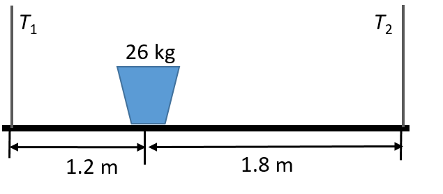
- The plank’s centre of gravity is halfway through its length (because the centre of gravity of a regular object is the same as its geometrical centre), therefore at [latex]\scriptsize \text{1}\text{.5 m}[/latex].
- The bucket of paint exerts its weight at [latex]\scriptsize \text{1}\text{.2 m}[/latex] from the edge of the plank.
- The weight of the bucket of paint is [latex]\scriptsize \displaystyle {{W}_{{\text{paint}}}}={{m}_{{\text{paint}}}}g=26.0\ \times \ 9.8=254.8\ \text{N}[/latex].
- The weight of the plank is [latex]\scriptsize \displaystyle {{W}_{{\text{plank}}}}={{m}_{{\text{plank}}}}g=15.0\ \times \ 9.8=147\ \text{N}[/latex].
Both conditions for equilibrium must be met. In other words, the sum of the forces must be equal as well as the sum of the torques.
For the sum of the vertical forces – the combined weight of the system and the tensions in the ropes:
[latex]\scriptsize \begin{align*}\Sigma {{F}_{{\text{vertical}}}}&=0\\{{T}_{1}}+{{T}_{2}}&=254.8+147=401.8\text{ N}\end{align*}[/latex] Equation 1
For the sum of the torques, take the system’s centre of gravity as the point of rotation and the clockwise torque as positive. Recall that torque is calculated as the product of the applied force and the perpendicular distance: [latex]\scriptsize \tau =F{{r}_{\bot }}[/latex].
[latex]\scriptsize \begin{align*}\Sigma \tau =0\\ \therefore {{T}_{1}}{{r}_{1}}+W{{r}_{\bot }}-{{T}_{2}}{{r}_{2}}&=0\\ [({{T}_{1}}\times 1.5)+(254.8\times 1.2)]-({{T}_{2}}\times 1.5)&=0\\ 1.5{{T}_{1}}-1.5{{T}_{2}}&=-305.76\text{ N} \end{align*}[/latex] Equation 2
To solve simultaneously, multiply Equation 1 by [latex]\scriptsize 1.5[/latex] and add the equations together. Thus:
[latex]\scriptsize \begin{align*}(1.5{{T}_{1}}+1.5{{T}_{2}})+(1.5{{T}_{1}}-1.5{{T}_{2}})&=(1.5\times 401.8)\ -305.76\ \text{N}\\\text{3}{{T}_{1}}&=296.94\ \text{N}\\\therefore {{\text{T}}_{\text{1}}}&=98.98\text{ }\text{N}\end{align*}[/latex]
We can now calculate [latex]\scriptsize {{T}_{2}}[/latex] by substituting [latex]\scriptsize {{T}_{1}}[/latex] into Equation 1:
[latex]\scriptsize \begin{align*}98.98+{{T}_{2}}&=401.8\text{ N}\\\therefore {{T}_{2}}&=401.8-98.98\\&=302.82\text{ }\text{N}\end{align*}[/latex]
We can use the same principle to solve problems that involve centre of gravity when non-parallel non-concurrent forces are at work. Work through activity 2.1 and example 2.2 to understand the principle.
Activity 2.1: Understand how non-parallel non-concurrent forces affect equilibrium
Time required: 10 minutes
What you need:
- an internet connection
- a tablet, smartphone or computer
- a notebook and pencil
What to do:
- Open the at this link.
Scroll down the page and then open the drawbridge simulation.
- Watch the introductory animation and then continue to the simulation.
- On the simulation page, set the starting conditions as follows:
- Let the forces show (switch slide to ‘On’) and also let the forces at the pivot show.
- Cart mass = [latex]\scriptsize 1000\text{ kg}[/latex]
- Cable angle = [latex]\scriptsize 45^\circ[/latex]
- Cart position = [latex]\scriptsize 20\text{ m}[/latex]
- Bridge length = [latex]\scriptsize 40\text{ m}[/latex]
Note the magnitudes of the forces at the pivot and the tension in the cable.
- Reduce the angle of the cable (e.g. to [latex]\scriptsize 30^\circ[/latex] ) and then increase it beyond the starting value (e.g. to [latex]\scriptsize 60^\circ[/latex]). What is the effect on the system?
- Reset the angle of the cable to the starting value ([latex]\scriptsize 45^\circ[/latex]). Reduce the cart position (e.g. to [latex]\scriptsize 10\text{ m}[/latex]) and then increase it (e.g. to [latex]\scriptsize 30\text{ m}[/latex]). What is the effect on the system?
- Reset the cart position to the starting value ([latex]\scriptsize 20\text{ m}[/latex]). Reduce the cart mass (e.g. to [latex]\scriptsize 600\text{ kg}[/latex]) and then increase it (e.g. to [latex]\scriptsize 1200\text{ kg}[/latex]). What is the effect on the system?
- Now change the angle of the cable, the cart position and the mass of the cart. What is the effect on the tension in the cable and the force experienced at the pivot?
What did you find?
- Step 4: The smaller the angle, the higher the tension in the cable to keep the system in equilibrium.
- Step 5: The further the cart is from the pivot point, the greater the torque exerted by the system (bridge + horse and cart), and subsequently the greater the tension in the cable.
- Step 6: The bigger the mass of the system (bridge + horse and cart), the larger the upward force will be required to balance the downward force of the weight. A larger downward force will create a large clockwise torque, which means the tension in the cable has to increase to create a sufficient counter-torque.
- Step 7: The combination of cart position, angle of the cable and the mass of the system (bridge + horse and cart) determines the tension in the cable and the forces experienced at the pivot.
Example 2.2
A beam that pivots at a point along a wall is supported by a cable that makes an angle of [latex]\scriptsize 27^\circ[/latex] with the horizontal. The beam has a mass of [latex]\scriptsize 30\text{ kg}[/latex] and is [latex]\scriptsize \text{4 m}[/latex] long. The cable is connected at a point [latex]\scriptsize \text{0}\text{.7 m}[/latex] from the end of the beam and a basket of rocks of mass [latex]\scriptsize \text{40 kg}[/latex] hangs at the end of the beam. Determine the tension in cable.
Solution
First draw a force diagram to visualise the problem:
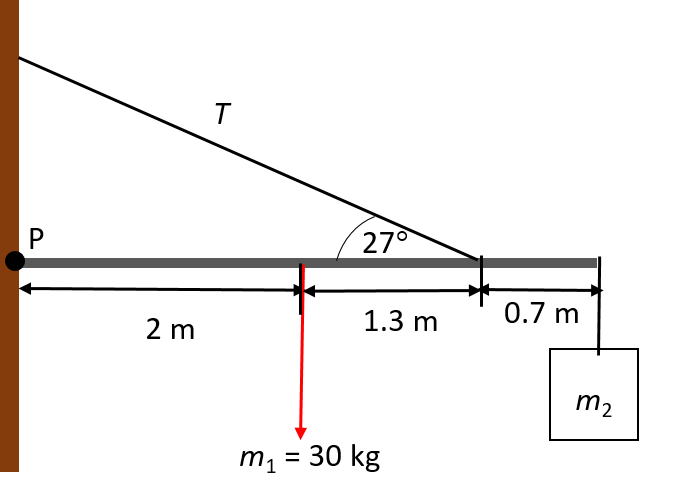
We note the following points before we start the calculation:
- Use the point P as the point of rotation.
- The weight of the beam acts through its centre of gravity, that is, halfway along the beam’s length.
- [latex]\scriptsize \displaystyle {{W}_{{\text{beam}}}}={{m}_{{\text{beam}}}}g=30\ \times \ 9.8=294\text{ N}[/latex]
- [latex]\scriptsize \displaystyle {{W}_{{\text{rocks}}}}={{m}_{{\text{rocks}}}}g=40\ \times \ 9.8=392\text{ N}[/latex]
- Take the clockwise moment as positive.
Remember that the vertical component [latex]\scriptsize T[/latex] represents the upward force, while the weight of the rocks and the beam act downwards.
For rotational equilibrium, the sum of the clockwise and anticlockwise moments must be zero: [latex]\scriptsize \displaystyle \Sigma \tau =0[/latex]. Therefore:
[latex]\scriptsize \displaystyle \begin{align*}\Sigma {{\tau }_{{\text{clockwise}}}}&=\Sigma {{\tau }_{{\text{anticlockwise}}}}\\ [(294\times 2)+(392\times 4)]&=[(T\sin 27^\circ )\times 3.3]\\2156&=1.5T\\\therefore T&=1437.3\text{ N}\end{align*}[/latex]
Exercise 2.1
- At a fruit vendor’s stall, two large baskets of fruit hang from a pole [latex]\scriptsize 2.2\ \text{m}[/latex] long. The one basket has a mass of [latex]\scriptsize \text{12 kg}[/latex] and hangs [latex]\scriptsize 1\ \text{m}[/latex] from the support. The other basket has a mass of [latex]\scriptsize \text{17 kg}[/latex]. The pole is perfectly balanced.
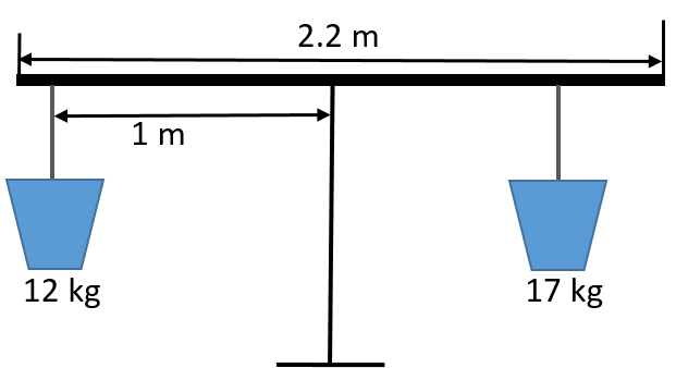
- How far from the support does the [latex]\scriptsize \text{17 kg}[/latex] basket hang?
- What is the tension in the ropes that support the two baskets?
- A drawbridge of mass [latex]\scriptsize 85\text{ kg}[/latex] and length [latex]\scriptsize 3.2\text{ m}[/latex] is lowered over a moat. If a man (mass = [latex]\scriptsize \text{72 kg}[/latex]) stands on the bridge [latex]\scriptsize \text{0}\text{.5 m}[/latex] from its end, what is the tension in the cable supporting the system if the cable makes an angle of [latex]\scriptsize 39^\circ[/latex] with the horizontal?
The full solutions are at the end of the unit.
Summary
In this unit you have learnt the following:
- A system that is balanced is not necessarily stable. For a system to be balanced and stable, the centre of gravity must be directly over the pivot point.
- An object’s centre of gravity is the point through which its weight acts.
- For a regular object, the centre of gravity is the same as the geometrical centre.
- We apply the two conditions for equilibrium to determine the variables involved in keeping a system in equilibrium and stable. This holds for both parallel and non-parallel non-concurrent forces.
Unit 2: Assessment
Suggested time to complete: 15 minutes
Questions 2 and 3 are from Chapter 9 in OpenStax Physics, p. 317–346 released under a CC-BY licence.
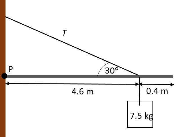
- Calculate the tension in the cable that supports a rigid beam [latex]\scriptsize \text{5}\text{.0 m}[/latex] long and which pivots about point P. A mass of [latex]\scriptsize \text{7}\text{.5 kg}[/latex] hangs [latex]\scriptsize \text{40 cm}[/latex] from the end of the beam. The cable makes an angle of [latex]\scriptsize 30^\circ[/latex] with the horizontal.
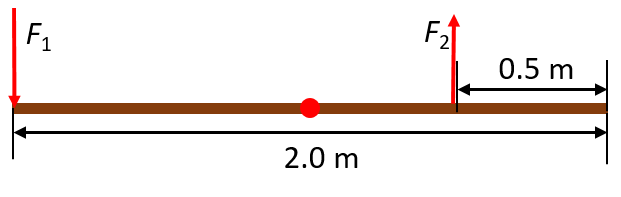
- A person carries a plank of wood [latex]\scriptsize \text{2}\text{.0 m}[/latex] long with one hand pushing down on it at one end with a force [latex]\scriptsize {{F}_{1}}[/latex] and the other hand holding it up at [latex]\scriptsize \text{0}\text{.5 m}[/latex] from the end of the plank with force [latex]\scriptsize {{F}_{2}}[/latex]. If the plank has a mass of [latex]\scriptsize \text{20}\text{.0 kg}[/latex] and its centre of gravity is at the middle of the plank, what are the magnitudes of the forces [latex]\scriptsize {{F}_{1}}[/latex] and [latex]\scriptsize {{F}_{2}}[/latex]?
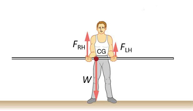
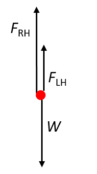
- A man holds a pole of [latex]\scriptsize 5.0\text{ kg}[/latex] as shown in the diagram. His hands are [latex]\scriptsize 90\text{ cm}[/latex] apart and the centre of gravity of the pole is [latex]\scriptsize 60\text{ cm}[/latex] from the left hand. Calculate the force exerted by each hand [latex]\scriptsize \text{(} {{F}_{{\text{RH}}}}[/latex] and [latex]\scriptsize {{F}_{{\text{LH}}}} \text{).}[/latex]
The full solutions are at the end of the unit.
Unit 2: Solutions
Exercise 2.1
- Both conditions for equilibrium must be met. In other words, the sum of the forces must be equal as well as the sum of the torques.
- .
[latex]\scriptsize \displaystyle \begin{align*}\Sigma {{\tau }_{{\text{clockwise}}}}&=\Sigma {{\tau }_{{\text{anticlockwise}}}}\\(12\times 9.8)(1)&=(17\times 9.8)r\\\therefore r&=0.7\text{ m}\end{align*}[/latex] - For the sum of the vertical forces, we take the combined weight of the system and the tensions in the ropes:
[latex]\scriptsize \begin{align*}\Sigma {{F}_{{\text{vertical}}}}&=0\\{{T}_{1}}+{{T}_{2}}&=(12\times 9.8)+(17\times 9.8)\\&=117.6+166.6\text{ N }\\&=284.2\text{ N}\end{align*}[/latex] Equation 1
.
For the sum of the torques, take the system’s centre of gravity as the point of rotation and the clockwise torque as positive. Recall that torque is calculated as the product of the applied force and the perpendicular distance: [latex]\scriptsize \tau =F{{r}_{\bot }}[/latex].
[latex]\scriptsize \displaystyle \begin{align*}\Sigma \tau &=0\\\therefore {{T}_{1}}{{r}_{1}}-{{T}_{2}}{{r}_{2}}&=0\\({{T}_{1}}\times 1.0)]-({{T}_{2}}\times 0.7)&=0\\\therefore 1{{T}_{1}}&=0.7{{T}_{2}}\end{align*}[/latex] Equation 2
.
Substituting Equation 2 into Equation 1:
[latex]\scriptsize \displaystyle \begin{align*}0.7{{T}_{2}}+{{T}_{2}}&=284.2\text{ N}\\\text{1}\text{.7}{{T}_{2}}&=284.2\text{ N}\\\therefore {{T}_{2}}&=167.18\text{ N}\end{align*}[/latex]
.
AND
.
[latex]\scriptsize \displaystyle \begin{align*}1{{T}_{1}}&=0.7{{T}_{2}}\\&=0.7(167.18)\\&=117.03\text{ N}\end{align*}[/latex]
- .
- For rotational equilibrium, the sum of the clockwise and anticlockwise moments must be zero: [latex]\scriptsize \displaystyle \Sigma \tau =0[/latex].
Therefore:
[latex]\scriptsize \displaystyle \begin{align*}\Sigma {{\tau }_{{\text{clockwise}}}}&=\Sigma {{\tau }_{{\text{anticlockwise}}}}\\(85\times 9.8)(1.6)+(72\times 9.8)(2.7)&=(T\sin 39^\circ )(3.2)\\1332.8+1905.1&=0.629T\\\therefore T&=5147.7\text{ N}\end{align*}[/latex]
Unit 2: Assessment
- For rotational equilibrium, the sum of the clockwise and anticlockwise moments must be zero: [latex]\scriptsize \displaystyle \Sigma \tau =0[/latex].
Therefore:
[latex]\scriptsize \displaystyle \begin{align*}\Sigma {{\tau }_{{\text{clockwise}}}}&=\Sigma {{\tau }_{{\text{anticlockwise}}}}\\(7.5\times 9.8)(4.6)&=(T\sin 30^\circ )(4.6)\\73.5&=0.5T\\\therefore T&=147\text{ N}\end{align*}[/latex] - Draw a diagram to visualise the problem:
.
Both conditions for equilibrium must be met. In other words the sum of the forces must be equal as well as the sum of the torques.
.
For the sum of the vertical forces – the combined downward force and the upward force:
[latex]\scriptsize \begin{align*}\Sigma {{F}_{{\text{vertical}}}}&=0\\ {{F}_{1}}+{{W}_{{\text{plank}}}}-{{F}_{2}}&=0\\ [{{F}_{1}}+(20\times 9.8)]-{{F}_{2}}&=0\\ \therefore {{F}_{1}}-{{F}_{2}}&=-196\text{ N}\end{align*}[/latex] Equation 1
.
For the sum of the torques, take the system’s centre of gravity as the point of rotation and the clockwise torque as positive. Recall that torque is calculated as the product of the applied force and the perpendicular distance:[latex]\scriptsize \tau =F{{r}_{\bot }}[/latex].
[latex]\scriptsize \displaystyle \begin{align*}\Sigma \tau &=0\\ \therefore {{F}_{1}}{{r}_{\bot }}+W{{r}_{\bot }}-{{F}_{2}}{{r}_{\bot }}&=0\\ [({{F}_{1}}\times 1.5)+(20\times 9.8\times 1)]-({{F}_{2}}\times 0.5)&=0\\ 1.5{{F}_{1}}-0.5{{F}_{2}}&=-196\text{ N}\end{align*}[/latex] Equation 2
.
To solve simultaneously, multiply Equation 1 by [latex]\scriptsize -2[/latex] and add the equations together. Thus:
[latex]\scriptsize \begin{align*}(-3{{F}_{1}}+{{F}_{2}})+{{F}_{1}}-{{F}_{2}})&=(-2\times 196)\ -196\ \text{N}\\-2{{F}_{1}}&=-588\ \text{N}\\\therefore {{F}_{\text{1}}}&=294\text{ }\text{N}\end{align*}[/latex]
.
We can now calculate [latex]\scriptsize {{F}_{2}}[/latex] by substituting [latex]\scriptsize {{F}_{1}}[/latex] into Equation 1:
[latex]\scriptsize \begin{align*}294-{{F}_{2}}&=-196\text{ N}\\\therefore {{F}_{2}}&=294+196\\&=490\text{ }\text{N}\end{align*}[/latex] - Draw a free-body diagram to visualise the problem:
.
We use the second condition for equilibrium ([latex]\scriptsize \Sigma \tau =0[/latex]) and choose the pivot point as either of the hands. This makes the torque from that hand zero. Let’s choose the left hand as the pivot.
.
There are now only two non-zero torques: those from the weight of the pole ([latex]\scriptsize \displaystyle {{\tau }_{\text{W}}}[/latex]) and from the push or pull of the right hand ([latex]\scriptsize \displaystyle {{\tau }_{{\text{RH}}}}[/latex]). We know that [latex]\scriptsize \Sigma {{\tau }_{{\text{clockwise}}}}=\Sigma {{\tau }_{{\text{anticlockwise}}}}[/latex]. In this case, [latex]\scriptsize {{\tau }_{{\text{RH}}}}=\Sigma {{\tau }_{\text{W}}}[/latex], as the weight of the pole creates an anticlockwise torque and the right hand counters with a clockwise torque. Using the definition of torque, [latex]\scriptsize \tau =F{{r}_{\bot }}[/latex] and substituting known values, we get:
[latex]\scriptsize \displaystyle \begin{align*}(0.9)({{F}_{{\text{RH}}}})&=(0.6)(mg)\\\therefore {{F}_{{\text{RH}}}}&=0.667(5.0)(9.8)\\&=32.7\text{ N}\end{align*}[/latex]
Remember to convert centimetres to metres for this calculation.
.
To calculate the force exerted by the left hand, we use the first condition for equilibrium, namely [latex]\scriptsize \Sigma F=0[/latex]. We see from the free-body diagram that [latex]\scriptsize \displaystyle {{F}_{{\text{RH}}}}+{{F}_{{\text{LH}}}}-mg=0[/latex]
Therefore:
[latex]\scriptsize \displaystyle \begin{align*}{{F}_{{\text{LH}}}}&=mg-{{F}_{{\text{RH}}}}\\&=(5.0)(9.8)-32.7\\&=49-32.7\\&=16.3\text{ N}\end{align*}[/latex]
Media Attributions
- PS 3_2.3_2_Img01a © OpenStax/Rice University is licensed under a CC BY (Attribution) license
- PS 3_2.3_2_Img01b © OpenStax/Rice University is licensed under a CC BY (Attribution) license
- PS 3_2.3_2_Img01c © OpenStax/Rice University is licensed under a CC BY (Attribution) license
- PS 3_2.3_2_Img02 © DHET is licensed under a CC BY (Attribution) license
- PS 3_2.3_2_Img03 © DHET is licensed under a CC BY (Attribution) license
- PS 3_2.3_2_Img04 © DHET is licensed under a CC BY (Attribution) license
- PS 3_2.3_2_Img05 © DHET is licensed under a CC BY (Attribution) license
- PS 3_2.3_2_Img06 © OpenStax/Rice University is licensed under a CC BY (Attribution) license
- PS 3_2.3_2_Img07 © DHET is licensed under a CC BY (Attribution) license
- PS 3_2.3_2_Img08 © DHET is licensed under a CC BY (Attribution) license
the point in an object through which its weight acts
