Magnetism and electricity: State, analyse and apply principles in electromagnetism
Unit 2: Electromagnetic induction
Leigh Kleynhans
Unit outcomes
By the end of this unit you will be able to:
- Describe and apply electromagnetic induction to produce current by changing the magnetic field.
- Describe how electromagnetic induction is applied in dynamos and transformers.
What you should know
Before you start this unit, make sure you can:
- Describe the magnetic field around a current-carrying conductor. You can refer to level 3, subject outcome 4.2, unit 1 to revise this.
- Use the right-hand (solenoid) rule. You can refer to level 3, subject outcome 4.2, unit 1 to revise this.
Introduction
Connecting a wire to a power supply is not the only way to produce a current. Electricity can also be induced in a wire by moving it in a magnetic field. This is known as .
An electromotive force (), voltage, is induced in a coil of wire when a bar magnet is pushed in or pulled out of it. Emfs of opposite signs are produced by motion in opposite directions, and the emfs are also reversed by reversing the poles of the magnet being pushed in or pulled out. The same results are produced if the coil is moved over the magnet and then off – It is the relative motion that is important. The faster the motion, the greater the induced emf, and there is no induced emf when the magnet is stationary relative to the coil.
Activity 2.1: Investigate electromagnetic induction
Time required: 10 minutes
What you need:
- internet access
What to do:
- Go to the simulation of Faraday’s Law.
Tick voltmeter and field lines.
- Slowly move the magnet into the coil of wire.
- Note what happens to the reading on the voltmeter when the magnetic field lines that are closer together (at the north and south poles) move through the wire, compared to when the middle of the magnet moves through the coil?
- Move the magnet into and out of the coil faster.
- Observe whether the speed at which you move the magnet inside of the coil has any effect on the voltage induced.
- Note that the needle on the voltmeter changes direction depending on whether the magnet is moved into or out of the coil.
- Switch the poles of the magnet and note the effect.
- Add a coil with fewer loops and note the effect on the induced voltage.
What did you find?
- A voltage is induced when a magnet moves relative to a coil of wire.
- There is no voltage if the magnet is stationary.
- The amount of voltage is affected by the speed at which the magnet moves and the number of loops in the coil.
- The voltmeter needle changes direction depending on whether the magnet is moved into or out of the coil, and which pole of the magnet is moving in or out. This is an indication that the current produced will change direction i.e. it will be .
Electromagnetic induction
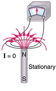
If a magnet is moved in and out of a solenoid, an emf (voltage) will be induced and consequently a current if the solenoid is in a closed circuit. No voltage or current is induced if the magnet is stationary. The electromagnetic induction depends on the changing magnetic field through the solenoid. In other words, the number of field lines passing through the coil is increasing or decreasing. If the number of field lines in the coil is constant, no emf or current is induced.
The direction of the induced current depends on which pole of the magnet is facing the solenoid and whether it is moving into or out of the solenoid. The induced current flows in a direction so as to set up a magnetic field to oppose the change in the magnetic field of the magnet.
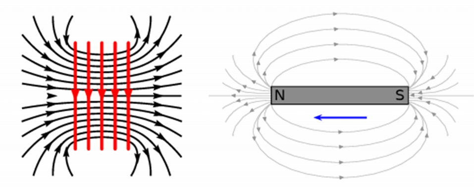
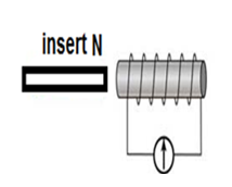
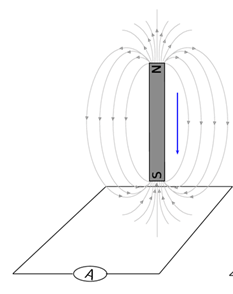
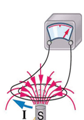
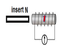
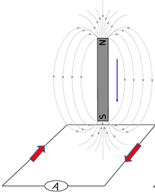
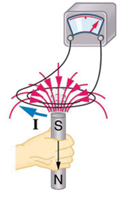
If the north pole of a magnet is moved into the solenoid (as in figure 1), the current in the solenoid will be induced to oppose this movement. In other words, current will flow in the solenoid to set up a magnetic field to repel the north pole, which means another north pole. You can use the right-hand (solenoid) rule: with your thumb pointing to north, your fingers curled around the solenoid will show you the direction of the induced current (up at the back and down in the front).
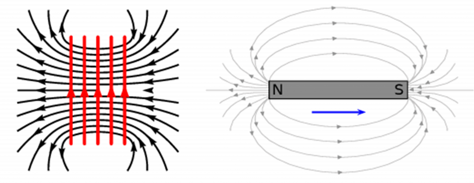
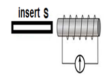
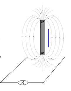
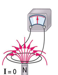
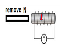
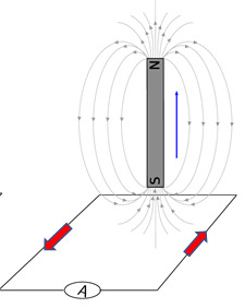
In the case where a north pole is moving away from the solenoid (repulsion), the current will flow so that a south pole is established at the end of the solenoid closest to the outward moving magnet to attract it. Using the right-hand (solenoid) rule, you can see that the current in the solenoid will be upwards in the front (as in figure 2 below).
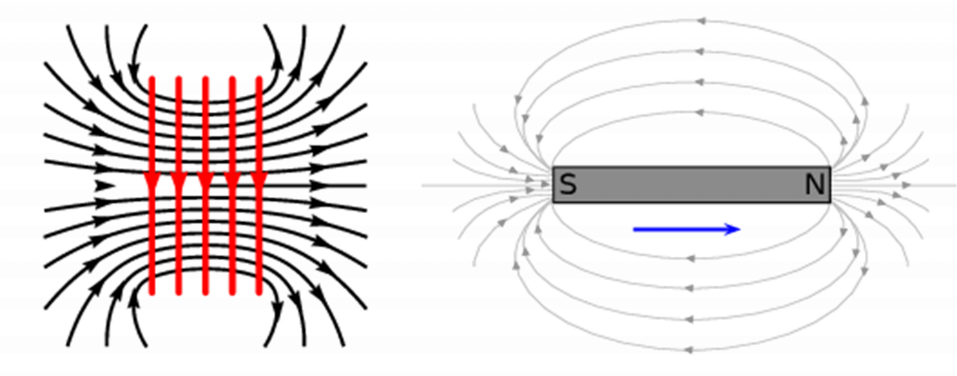
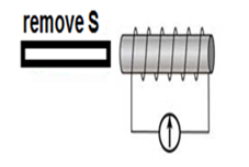
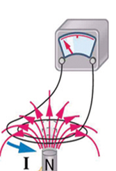
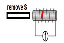
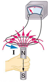
In the case where a south pole is moving away from the solenoid (repulsion), the current will flow so that a north pole is established at the end of the solenoid closest to the outward moving magnet to attract it. The current in the solenoid will be down in the front (see figure 3).
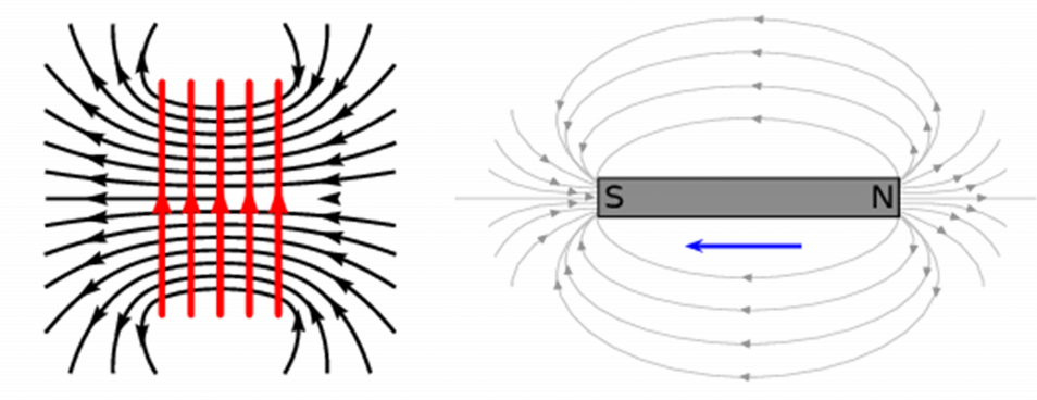
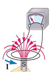
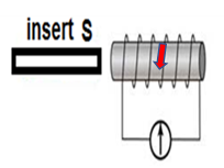
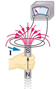
In the case where a south pole is brought towards the solenoid (attraction) the current will flow so that a south pole is established at the end of the solenoid closest to the approaching magnet to repel it. The current in the solenoid will be up in the front (see figure 4).
Exercise 2.1
Fill in the direction of the induced current on each solenoid:
- .
- .

- .
- .
The full solutions are at the end of the unit.
Dynamos (DC generators)
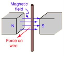
A converts kinetic energy into electrical energy. In a generator there is a magnetic field between two permanent magnets that is stationary, and a wire (or coil of wire) is moved within the field. The movement of the wire means the magnetic field, relative to the wire, changes so an emf will be induced and there will be current in the wire or coil. We can predict the direction of the induced current using .
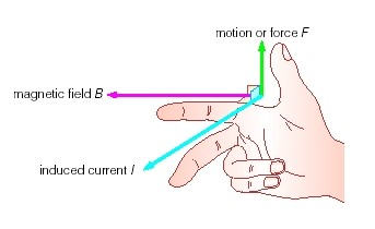
The thumb, index finger and middle finger of your right hand are held at right angles to each other. The thumb (F) is placed in the direction of the force (movement of the wire), the index finger (B) in the direction of the magnetic field (north to south) and the middle finger (I) will then point in the direction of the induced current.
Practise using Fleming’s right-hand (dynamo) rule to show that the current in the wire below will be upwards.
Exercise 2.2
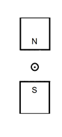
The pictures below are from a simple generator. Fill in the direction of the missing quantity (force, magnetic field or current) in these pictures using Fleming’s right-hand (dynamo) rule.
- .
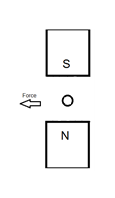
- .
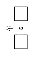
- .
The full solutions are at the end of the unit.
To generate a continuous flow of charge (current), a coil of wire is rotated in a magnetic field. One arm of the coil will be moving upwards while the other is moving downwards. The direction of movement of the arm of the coil changes every half rotation. Thus the current induced in the coil will be alternating current (AC).

In a , the alternating current induced in the coil is changed to in an external circuit by a device called a . The layout of a DC generator is shown in figure 8 below.
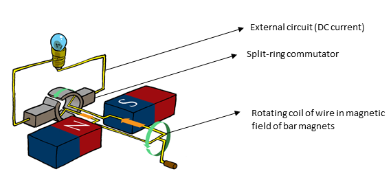
The current in the loop reverses direction but if you look carefully at the 2-D image (see figure 8) you will see that the section of the split-ring commutator also changes which side of the external circuit it is touching as it rotates. If the current changes direction at the same time that the commutator half-ring swaps sides, the external circuit will always have current going in the same direction – direct current (DC).
The speed at which the coil rotates in the magnetic field determines the amount of current generated. The faster the coil is turned, the greater the current induced. This can be seen practically on bicycle dynamos where the pedalling rotates a coil in a magnetic field to power a light. The faster you pedal, the brighter the light.
The current induced in a dynamo can also be increased by increasing the number of loops in the coil.
Note
As the functioning of a generator is based on movement, it is important that you watch the animation showing the process in this video called the Working Principle of DC Generator.
Transformers
The principle of electromagnetic induction is also used in . A transformer is an electrical device that is used to change high voltages to lower voltages or vice versa. Not all electrical appliances need the same voltage to operate properly, therefore transformers are used to convert the voltage supplied from power stations into a variety of voltages specific to the requirement of the electrical device.
How transformers work is based on the two concepts you have covered in this section on magnetism and electricity:
- When an electric current flows through a wire, it generates a magnetic field around it. The direction of the field is determined by the direction of the current. (As covered in Unit 1.)
- When there is a changing magnetic field around a coil of wire, it induces an emf and consequently an electric current in the wire. (As covered earlier in this unit.)
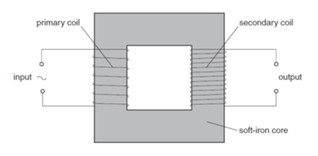
By using a source of alternating current (AC) in one coil of wire, the continuous direction change of the current will create a constantly changing magnetic field. So if we put a second coil of wire next to the first one, we will induce an emf and create an electric current in the second wire. The voltage in the first coil is usually called the and the voltage in the second wire is the . The current in the first coil () induces a current in the second coil (). We can make the changing magnetic field pass more efficiently from one coil to the other by wrapping them around a soft iron bar (sometimes called a ).
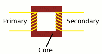
To make a coil of wire, we simply curl the wire round into loops or (‘’ as physicists like to call them). If the secondary coil has the same number of turns as the primary coil, the electric current in the secondary coil will be the same size as the one in the primary coil. But (and here is the clever part) if we have more or fewer turns in the second coil, we can make the secondary voltage bigger or smaller than the primary voltage.
One important thing to note is that this trick works only if the electric current is fluctuating in some way in the primary coil. In other words, you have to use alternating current (AC) in the primary coil of a transformer. Transformers do not work with direct current (DC), where a steady current constantly flows in the same direction as this will create a constant magnetic field and not a changing magnetic field.
Step-down transformers
If the primary coil has more turns that the secondary coil, the secondary voltage is smaller than the primary voltage.
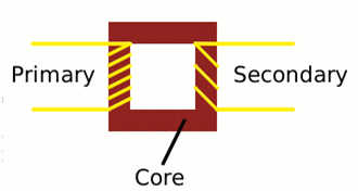
This is called a . If the secondary coil has half as many turns as the primary coil, the secondary voltage will be half the size of the primary voltage; if the secondary coil has one tenth as many turns, it has one tenth the voltage.
The current is transformed the opposite way: a decrease in the number of turns in the secondary coil results in an increase in current in the secondary circuit.
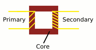
Step-up transformers
A boosts a low voltage into a high one, because there are more turns on the secondary coil than on the primary coil. The current in the secondary coil will be lower than the current in the primary coil.
Uses of transformers
There are transformers in towns and cities where the high voltage electricity from incoming power lines is converted into lower voltages. But there are many transformers in your home as well. Large electrical appliances such as washing machines and dishwashers use relatively high voltages of [latex]\scriptsize 110-240\text{ V}[/latex], but electronic devices such as laptop computers and mobile phones use relatively low voltages: a laptop needs about [latex]\scriptsize 15\text{ V}[/latex], an iPad charger about [latex]\scriptsize 12\text{ V}[/latex] and a mobile phone charger less than [latex]\scriptsize 6\text{ V}[/latex] when you charge the battery. So electronic appliances like these have small transformers built into them (often mounted at the end of the power cable) to convert the [latex]\scriptsize 110-240\text{ V}[/latex] domestic supply into a smaller voltage they can use.
Summary
In this unit you have learnt the following:
- An emf and current can be induced in a conductor by the process of electromagnetic induction.
- Electromagnetic induction involves a conductor placed in a changing magnetic field.
- A conductor can experience a changing magnetic field in two ways: by moving the conductor in a stationary magnetic field or moving a magnet relative to the conductor.
- The greater the speed of movement or the greater the number of loops in the conductor, the greater the induced emf and current.
- The direction of the induced current is such that it creates an electromagnet that opposes the changing magnetic field.
- The direction of the induced current can be determined using the right-hand (solenoid) rule.
- Generators consist of a coil rotated in a magnetic field, thus using electromagnetic induction to create electricity.
- The rotation of the coil induces alternating current (AC) because the movement of each arm of the coil changes from up to down every half rotation.
- In a dynamo the AC in the coil can be changed to DC in the external circuit by using a split-ring commutator.
- Fleming’s right-hand (dynamo) rule can be used to determine the direction of the induced current in each arm of the coil.
- Transformers use electromagnetic induction to change the voltage in a primary circuit into a different voltage in a secondary circuit based on the ratio of the number of turns in the primary coil to the number of turns in the secondary coil.
Unit 2: Assessment
Suggested time to complete: 30 minutes
- Magnets are moving relative to a coil of wire as illustrated in the diagrams below. Determine the direction of the induced current in the circuits.
- .
- .
- .
- A galvanometer is an instrument used to measure small amounts of current. The galvanometer needle gets deflected in the direction of the current. In the diagrams below, determine whether the magnet should be pushed into the coil or pulled out of the coil to induce current (I) in the direction shown.
- .
- .
- .
- .
- .
- Consider the following simplified diagram of a portion of the coil in a generator:
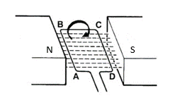
- The coil is rotated as shown. Will the current flow clockwise (ABCD) or anticlockwise (DCBA) initially?
- What will happen to the direction of the current if there is continuous rotation of the coil?
- Name and give the function of the apparatus that would be connected to the ends of the rotating coil of this generator to produce direct current in an external circuit.
- Give two ways in which the induced current in this generator could be increased.
- An ideal transformer is illustrated.
- Explain how electromagnetic induction is used in a transformer.
- Why will a transformer not operate using a direct current input.
- Give two examples of where you think transformers have had an impact.
- An American traveller in South Africa carries a transformer to convert South Africa’s standard [latex]\scriptsize 240\text{ V}[/latex] supply in wall sockets to [latex]\scriptsize 120\text{ V}[/latex] so that she can use some small appliances on her trip.
- What kind of transformer is she using?
- How could a South African travelling in the USA use this same transformer to power her [latex]\scriptsize 240\text{ V}[/latex] appliances from the [latex]\scriptsize 120\text{ V}[/latex] supply in the USA?
The full solutions can be found at the end of the unit.
Unit 2: Solutions
Exercise 2.1
If the magnet is moving towards the solenoid, the current will be induced in the direction that creates a pole to repel the magnet (use the right-hand solenoid rule).
If the magnet is moving out of the solenoid, the current will be induced in the direction that creates a pole that will attract the magnet (use the right-hand solenoid rule)
- .
- .
- .
- .
Exercise 2.2
Use Fleming’s right-hand (dynamo) rule:
- current is into the page
- South pole of magnet is on top
- force is to the left
Unit 2: Assessment
- .
- .
- .
Use the right-hand solenoid rule: curl your fingers in the current direction then your thumb will point to the north of the solenoid. Force must oppose this. In other words, if the solenoid’s pole is the same as the magnet’s this would be repulsion, so the movement of the magnet must be attraction (towards the solenoid). If the solenoid’s pole is opposite to the magnet’s this would be attraction, so the movement of the magnet must be repulsion (away from the solenoid).
- .
- .
- .
- .
- .
- .
- .
- .
- ABCD (Use Fleming’s right-hand dynamo rule)
- The current will change direction at regular intervals (every half rotation). So, alternating current (AC) is generated.
- Split-ring commutator
- Rotate the coil faster or increase the number of loops in the coil.
- .
- Alternating current in the primary coil creates a continuously changing magnetic field. This changing magnetic field induces an emf and current in the secondary coil. The soft iron core linking the primary and secondary coils enhances the changing magnetic effect.
- Direct current will create a fixed magnetic field. Electromagnetic induction only takes place when a magnetic field is changing all the time.
- Many different appliances can be used from a single voltage supply. Electricity can be distributed at high voltages around the country and then stepped down to individual homes and offices.
- .
- step-down transformer
- The transformer can be switched around so that the input power source is connected to the coil with fewer turns and the output circuit is connected to the coil with more turns. This effectively swops the primary and secondary coils around and the transformer will become a step-up transformer.
Media Attributions
- img01_Figure1 © Siyavula is licensed under a CC BY-NC-ND (Attribution NonCommercial NoDerivatives) license
- img02_Figure2 © Siyavula is licensed under a CC BY-NC-ND (Attribution NonCommercial NoDerivatives) license
- img03_Figure3 © Siyavula is licensed under a CC BY-NC-ND (Attribution NonCommercial NoDerivatives) license
- img04_Figure4 © Siyavula is licensed under a CC BY-NC-ND (Attribution NonCommercial NoDerivatives) license
- img05_Ex2.1 © L kleynhans is licensed under a CC BY (Attribution) license
- img05_Ex2.1 © L kleynhans is licensed under a CC BY (Attribution) license
- img05_Ex2.1 © L kleynhans is licensed under a CC BY (Attribution) license
- img05_Ex2.1 © L kleynhans is licensed under a CC BY (Attribution) license
- img06_Figure5 © Siyavula is licensed under a CC BY-NC-ND (Attribution NonCommercial NoDerivatives) license
- img07_Figure6 © L Kleynhans is licensed under a CC BY (Attribution) license
- img08_Ex2.2 © DHET is licensed under a CC BY (Attribution) license
- img08_Ex2.2 © DHET is licensed under a CC BY (Attribution) license
- img08_Ex2.2 © DHET is licensed under a CC BY (Attribution) license
- img09_Figure7 © DHET is licensed under a CC BY (Attribution) license
- img10_Figure8 © L Kleynhans is licensed under a CC BY (Attribution) license
- img11_Figure9 © L Kleynhans is licensed under a CC BY (Attribution) license
- img12_Figure10 © L Kleynhans is licensed under a CC BY (Attribution) license
- img13_Figure11 © L Kleynhans is licensed under a CC BY (Attribution) license
- img14_AssessmentQ1 © Siyavula is licensed under a CC BY-NC-ND (Attribution NonCommercial NoDerivatives) license
- img14_AssessmentQ1 © Siyavula is licensed under a CC BY-NC-ND (Attribution NonCommercial NoDerivatives) license
- img15_AssessmentQ2 © OpenStax is licensed under a CC BY (Attribution) license
- img15_AssessmentQ2 © OpenStax is licensed under a CC BY (Attribution) license
- img15_AssessmentQ2 © OpenStax is licensed under a CC BY (Attribution) license
- img15_AssessmentQ2 © OpenStax is licensed under a CC BY (Attribution) license
- img16_AssessmentQ3 © L Kleynhans is licensed under a CC BY (Attribution) license
- img17_AssessmentQ4 © L Kleynhans is licensed under a CC BY (Attribution) license
- img18_Ex2.1answers © L Kleynhans is licensed under a CC BY (Attribution) license
- img18_Ex2.1answers © L Kleynhans is licensed under a CC BY (Attribution) license
- img18_Ex2.1answers © L Kleynhans is licensed under a CC BY (Attribution) license
- img18_Ex2.1answers © L Kleynhans is licensed under a CC BY (Attribution) license
- img19_AssessmentQ1answers © Siyavula is licensed under a CC BY-NC-ND (Attribution NonCommercial NoDerivatives) license
- img19_AssessmentQ1answers © Siyavula is licensed under a CC BY-NC-ND (Attribution NonCommercial NoDerivatives) license
- img20_AssessmentQ2answers © Openstax is licensed under a CC BY (Attribution) license
- img20_AssessmentQ2answers © Openstax is licensed under a CC BY (Attribution) license
- img20_AssessmentQ2answers © Openstax is licensed under a CC BY (Attribution) license
- img20_AssessmentQ2answers © Openstax is licensed under a CC BY (Attribution) license
when the relative movement of a conductor and a permanent magnetic field is used to induce an emf in the conductor
the potential difference in electrical energy that causes charges to flow
a current that changes direction at regular intervals (the type that is generated in power stations)
a device that uses electromagnetic induction to produce electricity
the rule used to determine the direction of induced current in a generator
a generator in which the induced current is AC, but it is converted into DC in the external circuit
when the flow of charge (current) is in one direction only
a device used in a generator which converts the alternating current in the coil into direct current in the external circuit
electrical devices that use electromagnetic induction to change the voltage in a primary circuit to a different voltage in a secondary circuit
the voltage in the circuit of a transformer that is attached to a power source
the induced voltage in a separate circuit in a transformer that does not have a power source
the coil in a transformer attached to an AC power source
the coil in a transformer that does not have a power source
the component made of soft iron in a transformer that runs through both coils to enhance the magnetic effect
the loops of wire in a solenoid
a transformer that creates a lower voltage in the secondary circuit than in the primary circuit
a transformer that has a higher voltage in the secondary circuit than in the primary circuit
