Mechanics: Describe, analyse and apply principles of concurrent forces
Unit 1: Vector diagrams
Linda Pretorius
Unit outcomes
By the end of this unit you will be able to:
- Identify force as a vector.
- Construct vector diagrams of two forces to determine the relationship between the resultant and angle between forces (range [latex]\scriptsize 0^\circ[/latex]–[latex]\scriptsize 180^\circ[/latex]).
- Determine the resultant of two forces acting simultaneously on a body.
What you should know
Before you start this unit, make sure you can:
- Define a vector. Refer to level 2 subject outcome 2.1 unit 3 if you need help with this.
- Represent a vector graphically. Refer to level 2 subject outcome 2.1 unit 3 if you need help with this.
- Define the resultant of two vectors. Refer to level 2 subject outcome 2.1 unit 4 if you need help with this.
- Draw vector diagrams. Refer to level 2 subject outcome 2.1 unit 4 if you need help with this.
- Define a force. Refer to level 2 subject outcome 2.2 unit 1 if you need help with this.
Introduction
Parts of the text in this unit were sourced or adapted from Siyavula Physical Science Gr 11 Learner’s Book, p. 3–36, released under a CC-BY licence.
In this unit you will apply your knowledge of vectors in the context of forces by constructing vector diagrams for concurrent forces. Drawing vector diagrams will help you to understand the effect of two forces acting on a body simultaneously.
Force is a vector
We can think of a force being a push or a pull exerted on an object. But it is important to remember that this kind of push or a pull is the result of one object interacting with another, whether through direct contact (contact forces) or acting over a distance (non-contact forces).
In Level 2, you learnt that force is a quantity: it has both magnitude (size) and direction. Forces are additive, like all vector quantities. That means that if two are acting on an object, the net effect will be a combination of the two forces’ magnitude and direction. This net effect is called the .
Representing concurrent forces: Vector diagrams
From Level 2, you also know that vectors can be represented graphically using arrows, with the length of the arrow representing the magnitude and the arrowhead indicating the direction. It follows then that forces can be represented graphically as arrows, and that the combination of two forces can be presented in a diagram to find the resultant force.
Note
When drawing vector diagrams, we often refer to the head and the tail of the arrow representing the vector:
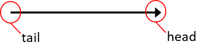
When two forces act in one dimension – in other words, in a straight line – the resultant force is simply the algebraic sum of the two forces. Because the forces are acting in one dimension, we can define one direction – for example, to the right – as positive, and the opposite direction –to the left – as negative.
Example 1.1
Use the graphical tail-to-head method to determine the resultant force on a rugby player if two players on his team are pushing him forward with forces of [latex]\scriptsize \overrightarrow{{{{F}_{1}}}}=600\ \text{N}[/latex] and [latex]\scriptsize \overrightarrow{{{{F}_{2}}}}=900\ \text{N}[/latex], respectively, and two players from the opposing team are pushing him backward with forces of [latex]\scriptsize \overrightarrow{{{{F}_{3}}}}=1\ 000\ \text{N}[/latex] and [latex]\scriptsize \overrightarrow{{{{F}_{4}}}}=650\ \text{N}[/latex], respectively.
Solution
Let’s choose a scale of [latex]\scriptsize 0.5\text{ cm}[/latex] representing [latex]\scriptsize 100\text{ N}[/latex] and define the positive direction as to the right.
Draw each vector in the relevant direction and at the correct length. In the explanation, we use different colours to distinguish between the four forces that are acting on the object. Therefore:
- [latex]\scriptsize \overrightarrow{{{{F}_{1}}}}[/latex] is drawn as an arrow of [latex]\scriptsize 3\text{ cm}[/latex] pointing to the right.
- [latex]\scriptsize \overrightarrow{{{{F}_{2}}}}[/latex] is drawn as an arrow of [latex]\scriptsize \text{4}\text{.5 cm}[/latex] pointing to the right.
- [latex]\scriptsize \overrightarrow{{{{F}_{3}}}}[/latex] is drawn as an arrow of [latex]\scriptsize \text{5 cm}[/latex] pointing to the left.
- [latex]\scriptsize \overrightarrow{{{{F}_{4}}}}[/latex] is drawn as an arrow of [latex]\scriptsize \text{3}\text{.25 cm}[/latex] pointing to the left.
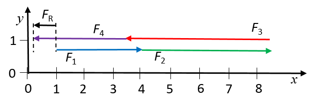
The resultant force, [latex]\scriptsize \overrightarrow{{{{F}_{\text{R}}}}}[/latex] is represented by an arrow of [latex]\scriptsize 0.75\text{ cm}[/latex] to the left, which, according to the scale used in the diagram, represents a force of [latex]\scriptsize 150\text{ N}[/latex].
When two forces act in two dimensions – in other words, not in a straight line – the resultant force is still found by adding the two vectors, but we now have to take the directions of the two individual forces into account. This means that the magnitude of the resultant force will not be the simple algebraic sum of the two vectors.
Vector diagrams are useful in determining the resultant force of two concurrent forces, and we can draw these diagrams as either tail-to-head or tail-to-tail diagrams. The approach is to draw the vectors one at a time.
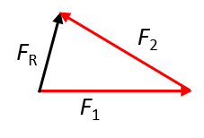
- In the tail-to-head method, each vector is drawn from the head of the vector that preceded it. The resultant vector is drawn from the tail of the first vector to the head of the second vector.
- In the tail-to-tail method, each vector, including the resultant, is drawn from the same origin. This is also called the parallelogram method.
Let’s look at examples of drawing vector diagrams for two forces that are perpendicular to each other using these methods.
Note
The tail-to-tail method is also called the parallelogram method as the vector diagram it creates is a parallelogram.
Example 1.2
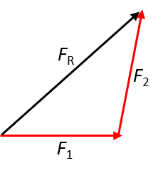
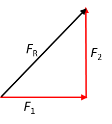
Sketch the resultant of the following forces using the tail-to-head method:
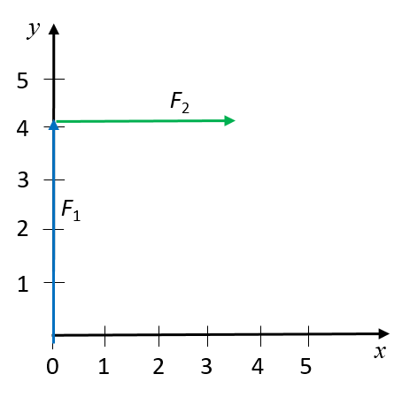
- [latex]\scriptsize \overrightarrow{{{{F}_{1}}}}=4.1\text{ N}[/latex] in the positive y-direction
- [latex]\scriptsize \overrightarrow{{{{F}_{2}}}}=3.5\text{ N}[/latex] in the positive x-direction.
Solution
Let’s define the positive x-direction as to the right, and the positive y-direction as up.
We can then represent the two forces as follows on a Cartesian plane:+
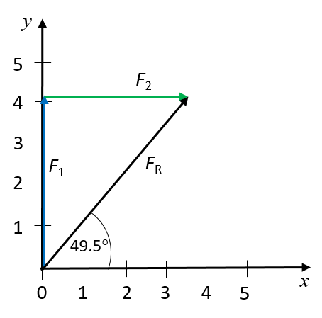
The resultant force is drawn by connecting the tail of the first arrow to the head of the second arrow. The resultant force is measured as [latex]\scriptsize 5.7\text{ N}[/latex] at a direction of [latex]\scriptsize 49.5^\circ[/latex] from the positive x-axis.
Example 1.3
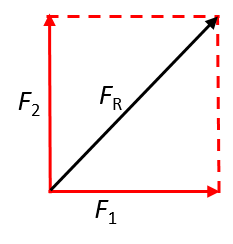
Sketch the resultant of the following forces using the tail-to-tail (parallelogram) method:
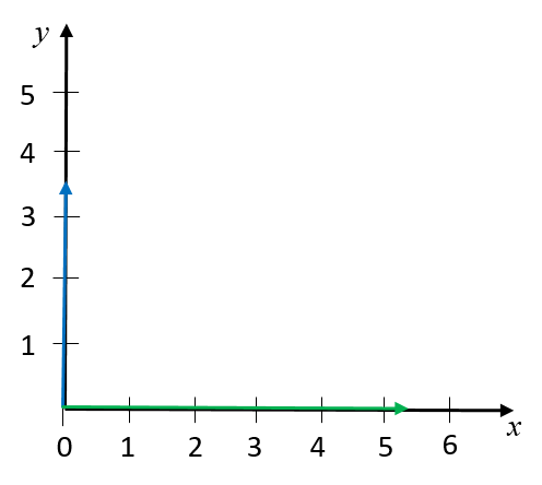
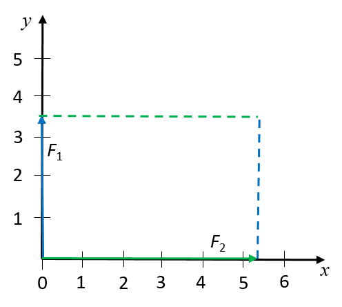
- [latex]\scriptsize \overrightarrow{{{{F}_{1}}}}=3.5\text{ N}[/latex] in the positive y-direction
- [latex]\scriptsize \overrightarrow{{{{F}_{2}}}}=5.2\text{ N}[/latex] in the positive x-direction.
Solution
Let’s define the positive x-direction as to the right, and the positive y-direction as up.
We can draw the two forces on a Cartesian plane, with both their tails at the origin.
We then draw a dashed line from the head of each vector, parallel to the other.
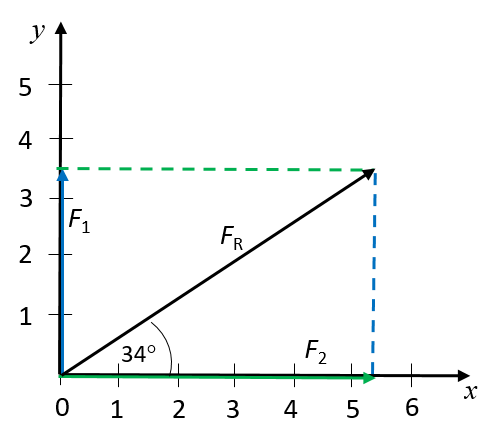
The resultant force is drawn as an arrow from the origin of the two vectors to the point where the dashed lines intersect. The resultant force is measured as [latex]\scriptsize 6.3\text{ N}[/latex] at a direction of [latex]\scriptsize 34^\circ[/latex] from the positive x-axis.
You already know that the resultant force is a force that represents the net effect of two concurrent forces. In activity 1.1, you will explore the effect of two concurrent forces acting on an object. Activity 1.2 is an extension activity, in which you will explore how the angle between two concurrent forces acting in two dimensions affects the resultant.
Activity 1.1: Determine the resultant of two concurrent forces
Time required: 15 minutes
What you need:
- a regular object (e.g. a textbook or a wooden block)
- string and scissors
- a marker pen, a sheet of paper and sticky tape
- a flat, fairly smooth surface
- a ruler
What to do:
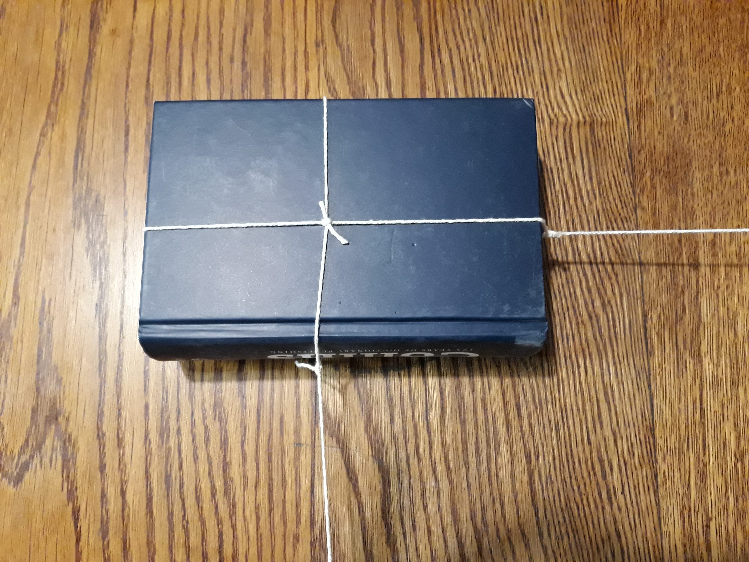
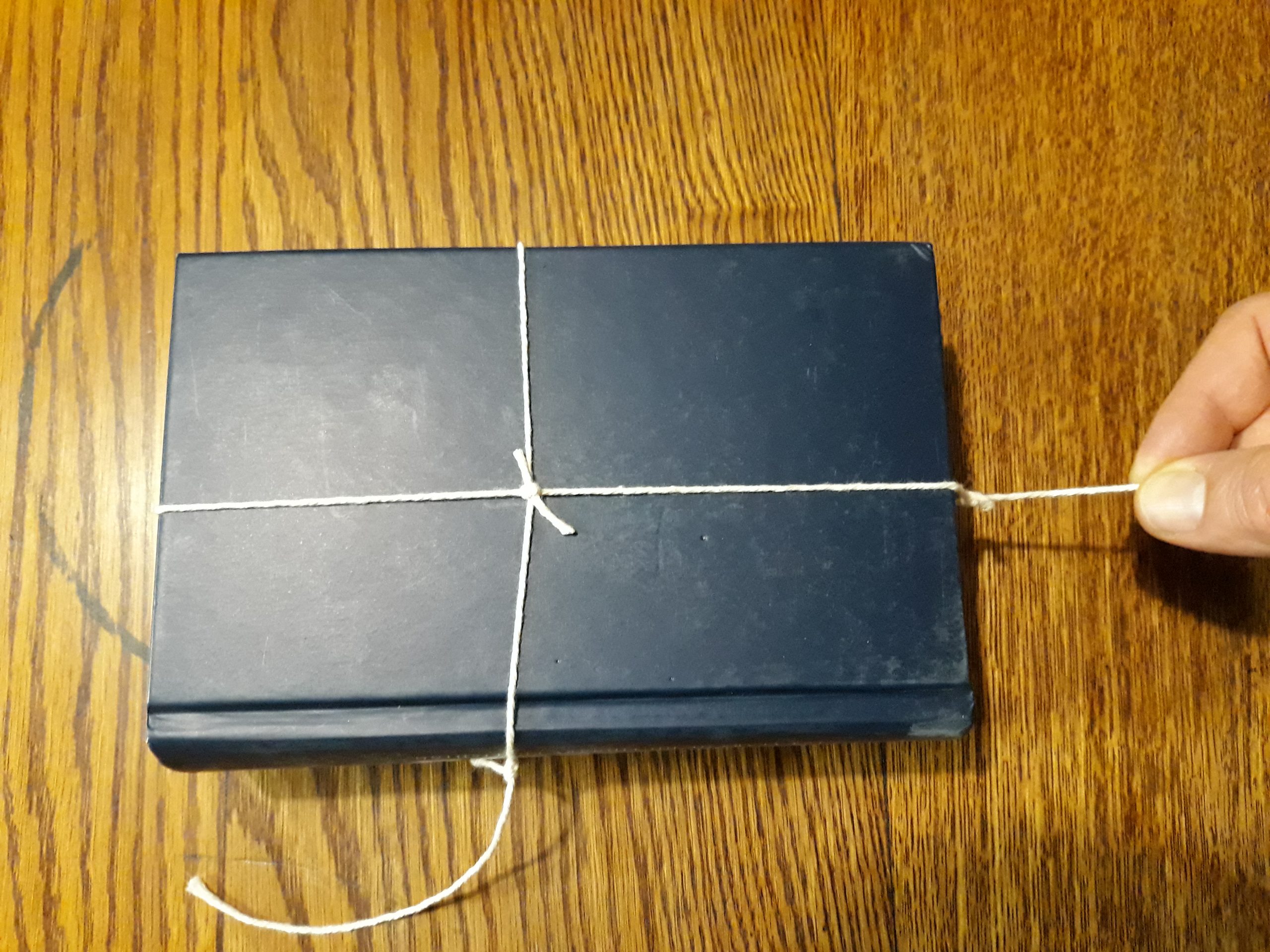
- Use the string to make a ‘harness’ around the object. Then tie a piece of string to each of two perpendicular sides, to serve as ‘handles’.
- Place the object on a flat surface. Pull the object sideways, keeping it flat along the surface.
- What do you observe?
- What happens when you pull harder on the string?
- What happens when you pull only gently?
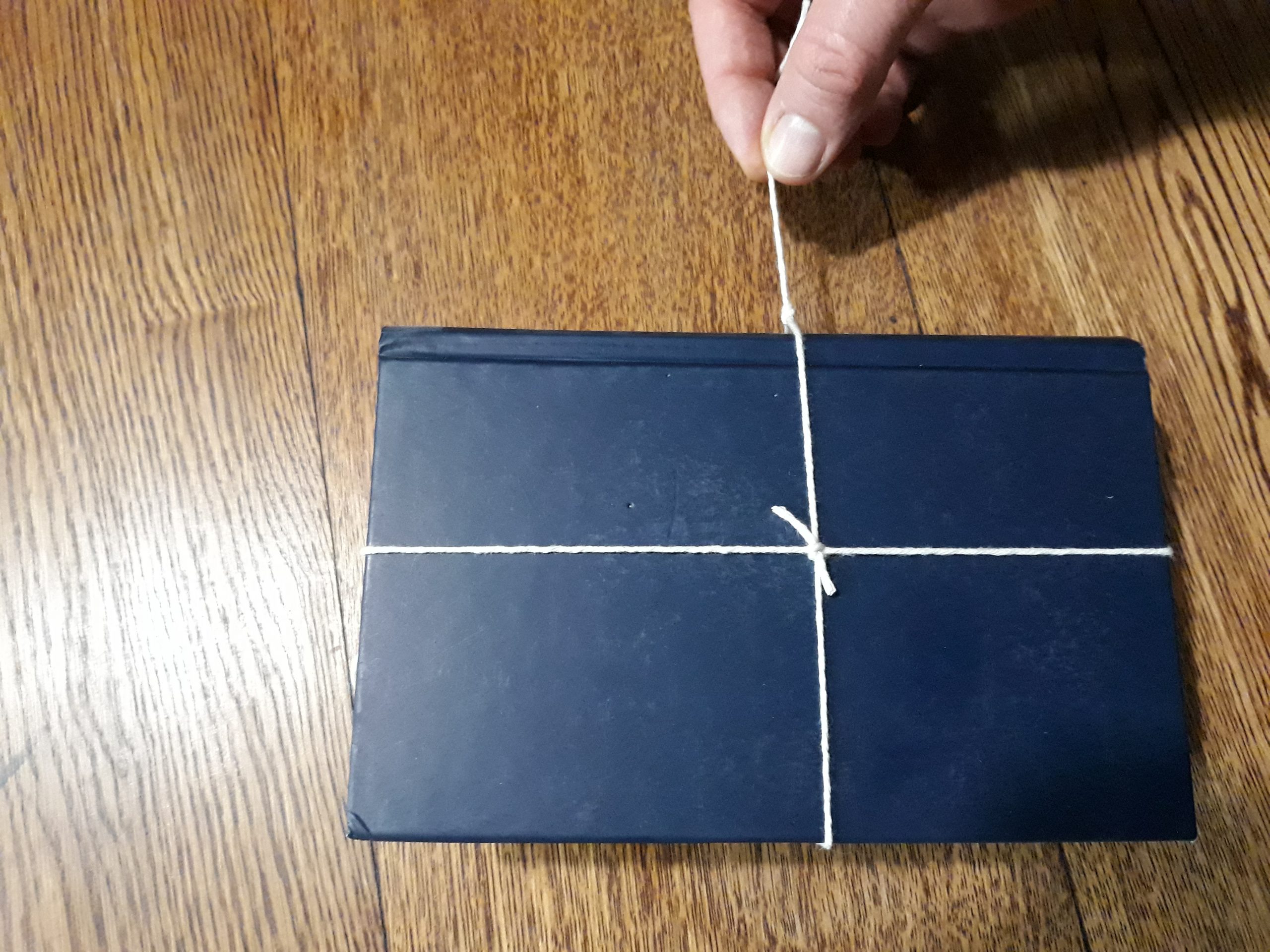
- Repeat what you did in step 2, but now using the other handle to pull the object in a vertical direction. Describe your observations.
- What can you conclude about the properties of a force that acts on an object?
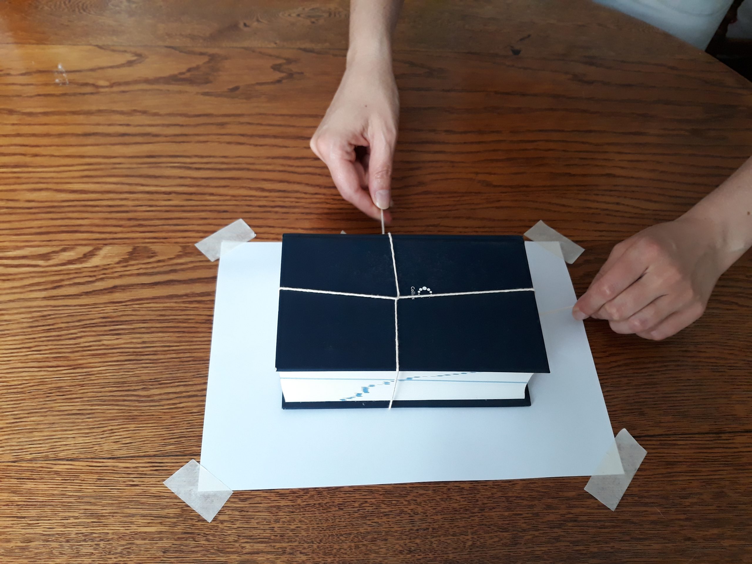
- Now place the object on the sheet of paper which is fixed to the flat surface. Mark the starting position of the object. Then pull on both handles at the same time, at a right angle. Try to pull equally hard on both handles. Mark the object’s final position.
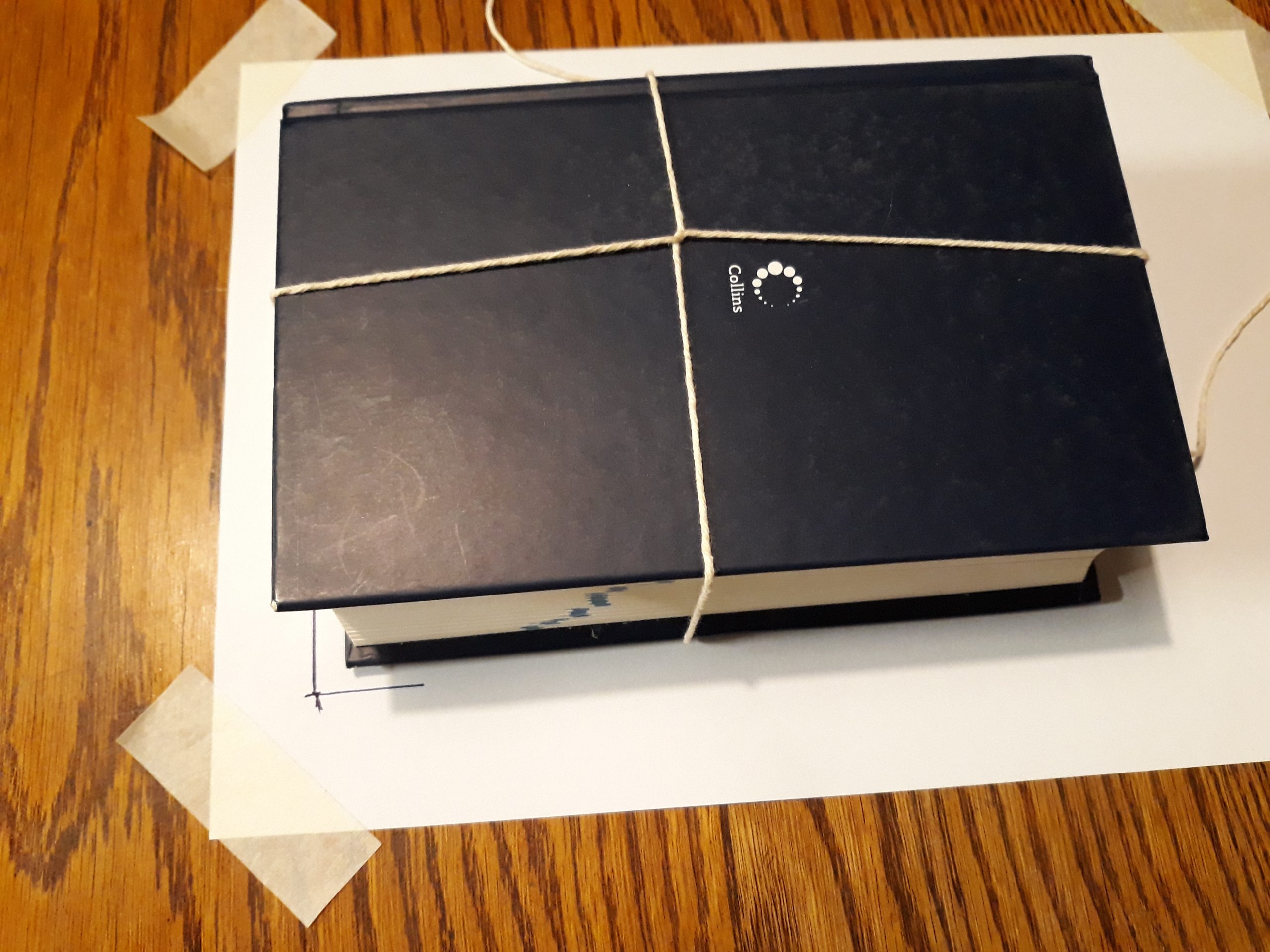
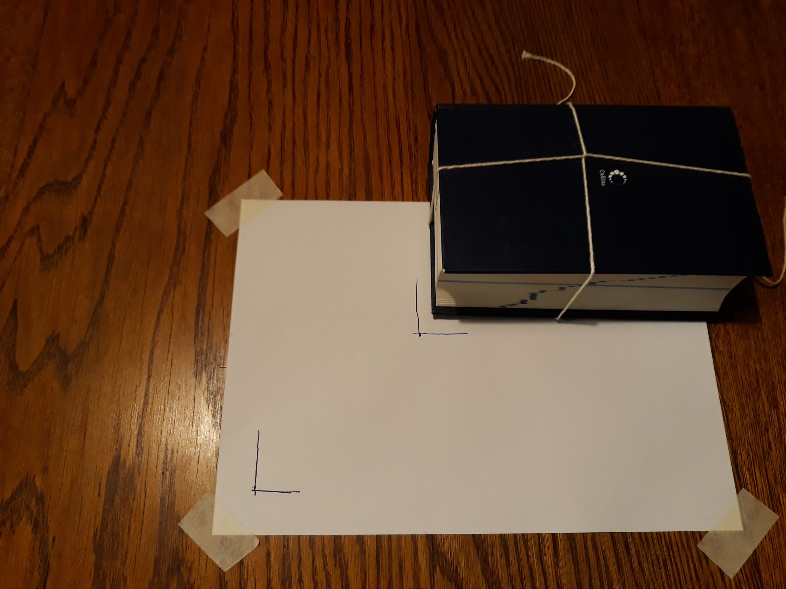
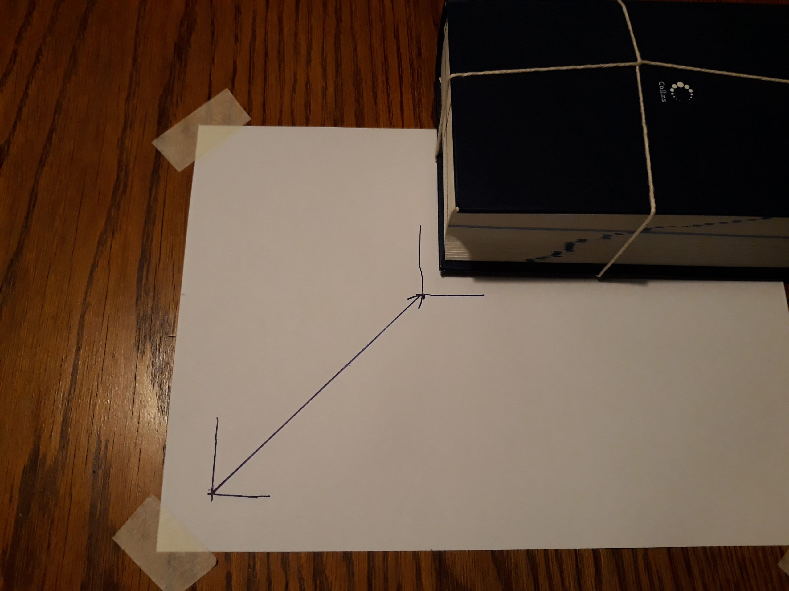
- Where did the object end up relative to its starting position? On the paper, draw an arrow to show this. Why do you think the object ended up in this position?
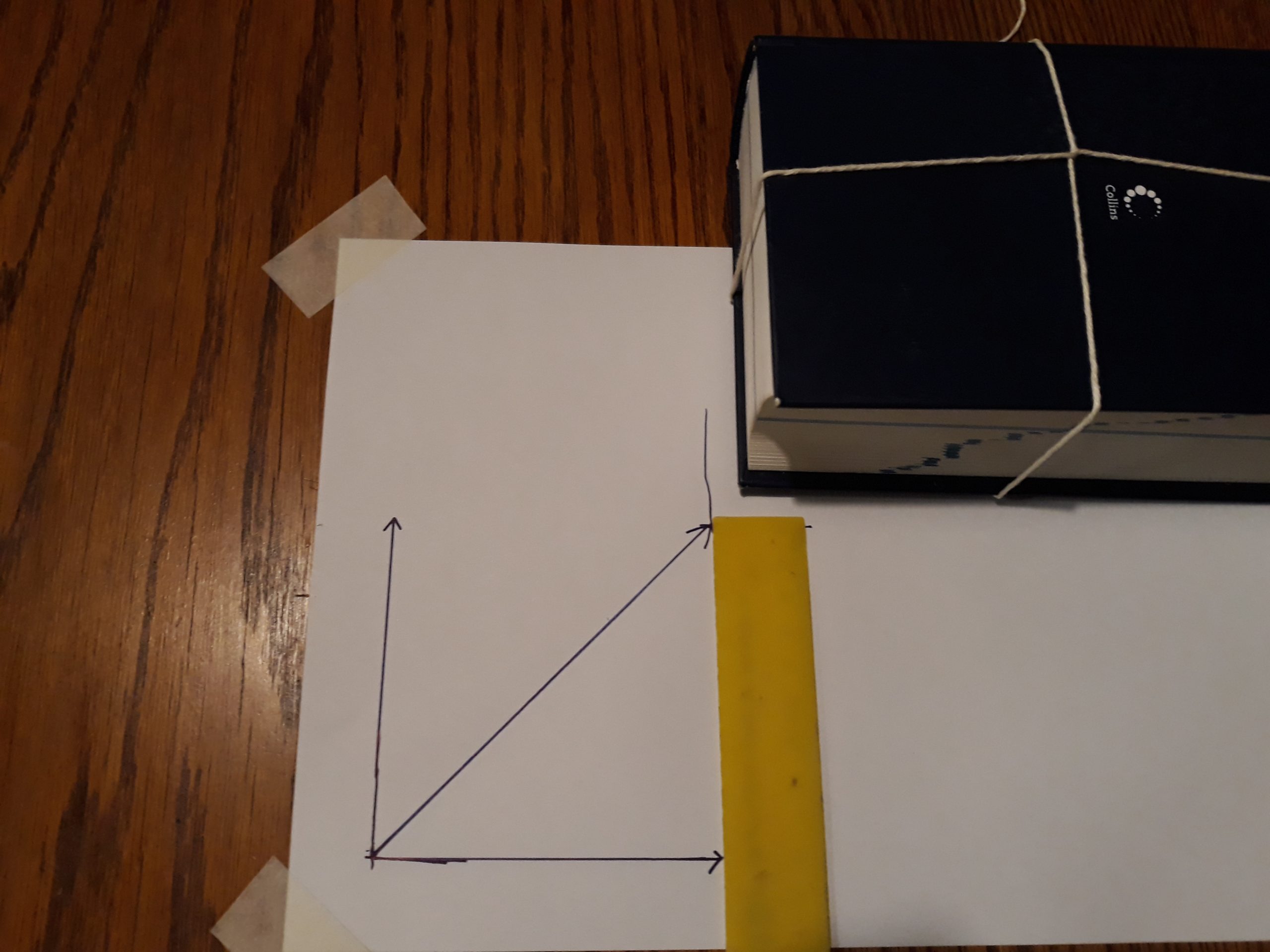
- Now draw arrows to show the two forces you applied. Align the end points of these arrows with the final position.
- Measure the length of each arrow that represents your pull forces, as well as the length of the diagonal arrow. (The diagonal arrow represents the net force, called the resultant.) Which arrow is the longest?
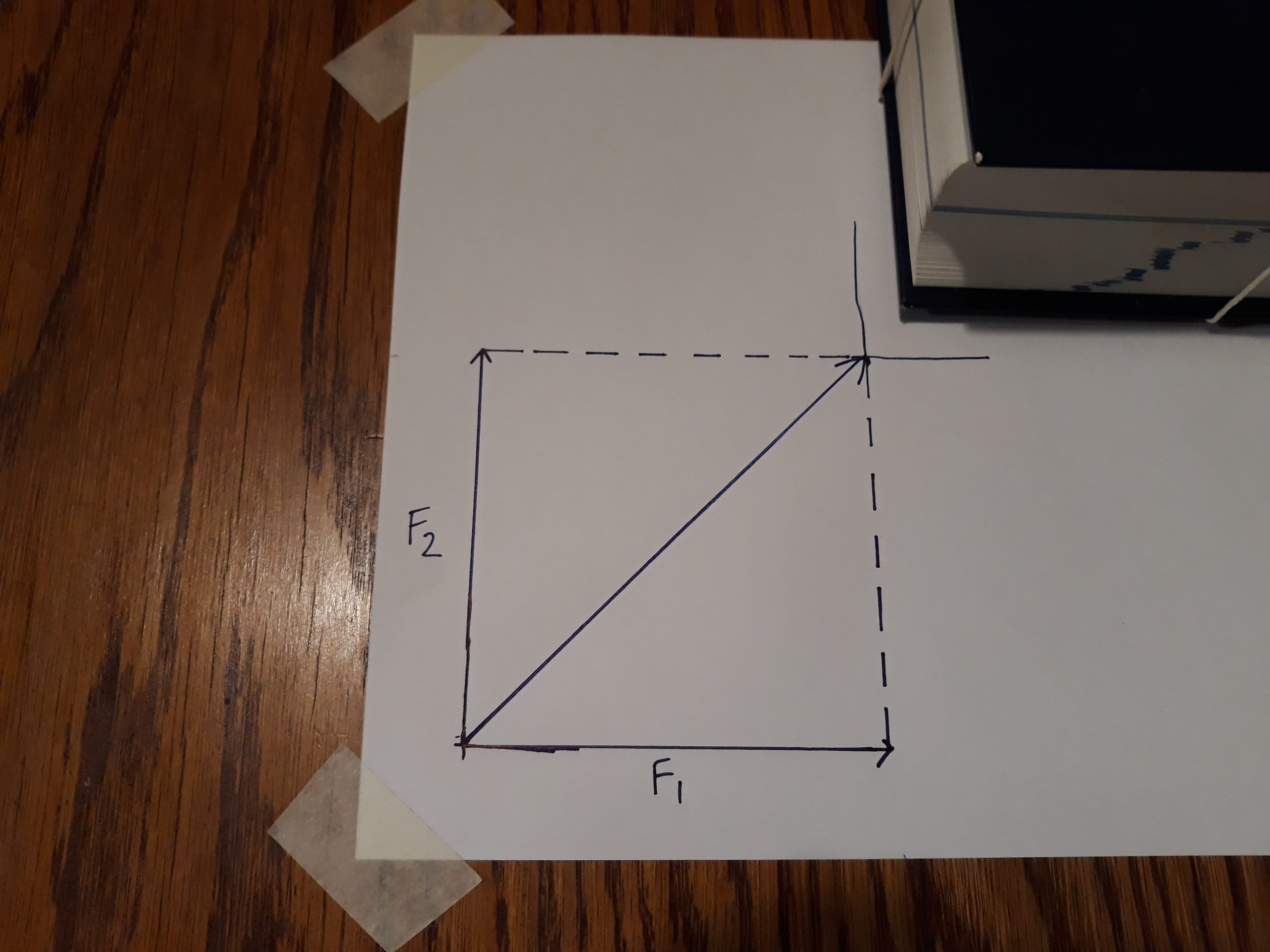
- Draw dashed lines to connect the tips of the applied forces to the object’s final position (in other words, the tip of the resultant). What shapes do you see?
What did you find?
Step 2. When the object is pulled sideways, it moves in the direction it is pulled. If you pull harder, the object moves faster. If you pull only gently, the object does not move as fast as before.
Step 3. When you pulled the object in an upward direction, you would have seen a similar effect: the object now simply moved in a vertical direction. This shows that the direction and size of the applied force determine the end result.
Step 4. From these two observations you can conclude that force (as applied here in the form of a pull) has a direction – you can see that from the change in the object’s position. Force also has magnitude, because you could apply a bigger or smaller force to make the object move faster or slower. Force is a vector: it has both magnitude and direction.
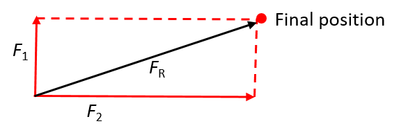
Step 5a. When you pulled on both handles simultaneously, the object came to rest at a position that is at an angle from the starting position.
The two forces acted in different directions. However, because they acted on the same object, the net force – the resultant – is in a direction between the two applied forces.
The lengths of the arrows representing the two applied forces will depend on how far you pulled the object, but they should be almost equal if you pulled with similar force in both directions. In the picture shown here the lengths are [latex]\scriptsize 9.4\text{ cm}[/latex] each. The diagonal arrow is [latex]\scriptsize 13.2\text{ cm }[/latex] in this example, but your answer will be specific to your drawing. The diagonal arrow (resultant) is longer than either of the two applied forces, because it represents the vector sum of the two applied forces. It is important to note that the magnitude is NOT the simple arithmetic sum of the two applied forces, because the two forces do not act in the same line. You will learn how to calculate the sum analytically in the next unit.
Step 5b. Having drawn dashed lines to connect the tips of the applied forces to the tip of the resultant, you can see two triangles, which together form a rectangle. (Remember that a rectangle is a type of parallelogram.) Noting these shapes is an important observation to help you draw vector diagrams, as you will see in activity 1.2 when you learn how to use either the tail-to-head (triangle) or parallelogram method for calculating the resultant force analytically.
Activity 1.2: Investigate the effect of the angle between forces on the resultant
Time required: 10 minutes
What you need:
- the same set-up and materials as in activity 1.1
What to do:
- Put the object at the starting position again. What do you think will happen if you pull with unequal force on the two strings? Try it out.
- .
- If you simultaneously pull the object directly eastwards and in a direction west of north, will the angle between the two applied forces be greater or smaller than [latex]\scriptsize 90^\circ[/latex]? Where do you think the object will end up? (Take upwards as north and to the right as east.)
- If you simultaneously pull the object directly eastwards and in a direction east of north, will the angle between the two applied forces be greater or smaller than [latex]\scriptsize 90^\circ[/latex]? Where do you think the object will end up? (Take upwards as north and to the right as east.)
Draw sketch diagrams to show your findings in steps 1 and 2 visually. Use what you have learnt in activity 1.1 to help you. How does the length of the arrow representing the resultant compare with that of the other two forces?
- What can you conclude about the relationship between the resultant and the angle between the two simultaneously applied forces?
What did you find?
- Step 1 showed that the size of the forces you apply determine where the object ends up relative to its starting position.
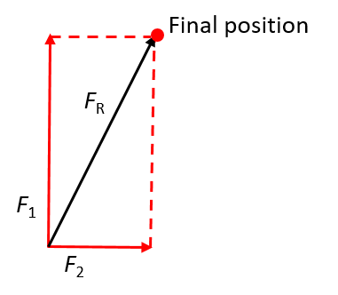
If you pull hard to the side and only a little in the vertical direction, the object will move along a flat gradient. In other words, the angle between the resultant and the horizontal will be small.
In contrast, if you pull hard in the vertical direction and only a little to the side, the object will move along a steep gradient. In other words, the angle between the resultant and the horizontal will be large.
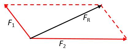
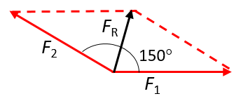
- and 3. Step 2a) showed that when two forces are applied concurrently directly eastwards and west of north, the angle between the two applied forces is greater than [latex]\scriptsize 90^\circ[/latex](but smaller than [latex]\scriptsize 180^\circ[/latex]). By using the tail-to-tail (or parallelogram) method of drawing a vector diagram, we see that a parallelogram is formed. In this case, the arrow representing the resultant will be shorter than the longer of the two representing the applied forces. This means the magnitude of the resultant is smaller than the bigger of the two applied forces.
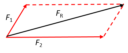
However, if the angle between the two applied forces is [latex]\scriptsize \le 90^\circ[/latex], as in Step 2b), the magnitude of the resultant will be greater than that of either of the applied forces, as we can see by using the tail-to-tail method of drawing vector diagrams.
Exercise 1.1
- Describe the following forces. Use compass directions or angles to state the direction, as applicable. Take the upward direction as north.
- .
- .
- .
- .
- Are the following statements true or false? Explain your reasoning.
- When two forces act in different directions, the magnitude of the resultant will be the arithmetic sum of the two separate magnitudes.
- When two forces act concurrently on an object at right angles, the angle of the resultant force will be greater than [latex]\scriptsize 90^\circ[/latex].
- When two forces act on an object, one directly east and another north-west, the resultant force will be south-west.
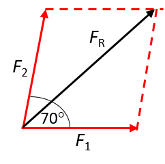
- Draw a vector diagram to show the resultant of two concurrent forces of equal magnitude in the following cases. You can use either the tail-to-head method or the tail-to-tail (parallelogram) method.
- When the angle between the two forces is [latex]\scriptsize 70^\circ[/latex].
- When the angle between the two forces is [latex]\scriptsize 90^\circ[/latex].
- When the angle between the two forces is [latex]\scriptsize 150^\circ[/latex].
The full solutions can be found at the end of the unit.
Summary
In this unit you have learnt the following:
- Force is a vector quantity. It has both magnitude and direction.
- The resultant force is a single force that represents the net effect of two forces.
- Because forces are additive, like all vectors, the resultant force is found by combining the effects of the respective individual forces.
- When two forces act in different dimensions, the resultant cannot be taken as the simple arithmetic sum of the two individual forces, as the direction of each individual force has to be taken into account:
- When the angle between the two forces is [latex]\scriptsize \le 90^\circ[/latex], the magnitude of the resultant will be greater than that of either of the applied forces.
- When the angle between the two applied forces is greater than [latex]\scriptsize 90^\circ[/latex](but smaller than [latex]\scriptsize 180^\circ[/latex]), the magnitude of the resultant will be smaller than the bigger of the two applied forces.
Unit 1: Assessment
Questions 1–4 are taken from Exercise 1-7 in the Siyavula Gr 11 Physical Science Learner’s Book on pp. 50–53, released under a CC-BY licence
Suggested time to complete: 15 minutes
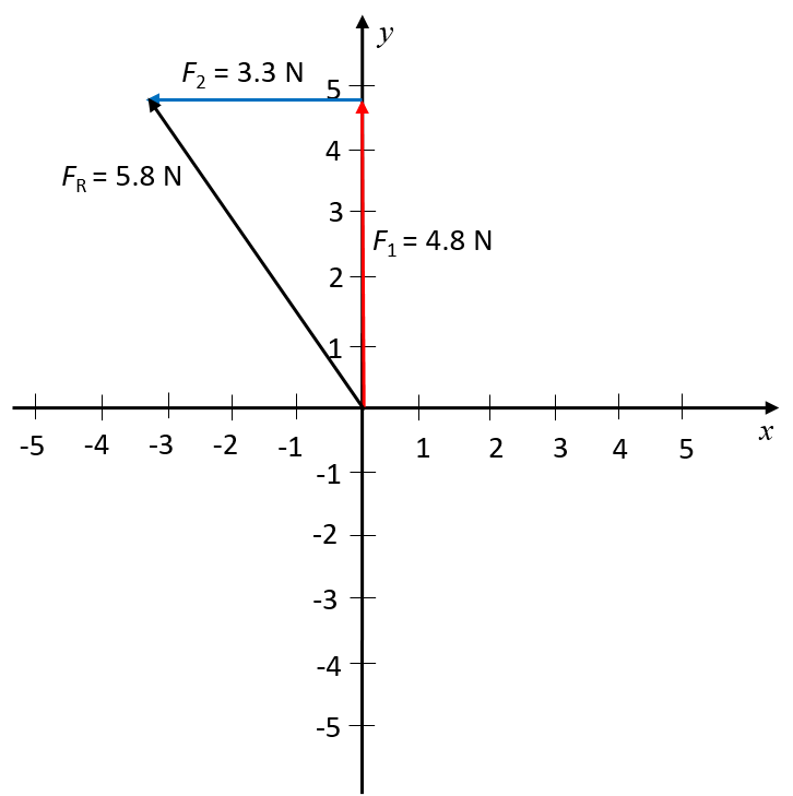
- Sketch the resultant of the following concurrent force vectors using the tail-to-head method:
- [latex]\scriptsize \overrightarrow{{{{F}_{1}}}}=4.8\text{ N}[/latex] in the positive y-direction
- [latex]\scriptsize \overrightarrow{{{{F}_{2}}}}=3.3\text{ N}[/latex] in the negative x-direction
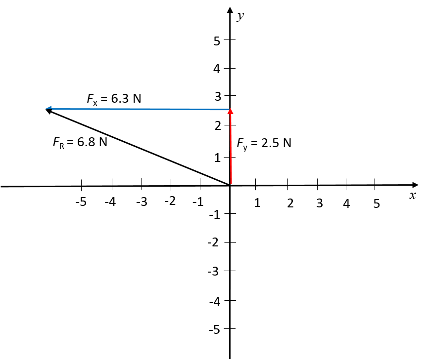
- Sketch the resultant of the following concurrent force vectors using the tail-to-head method by first determining the resultant in the x- and y-directions:
- [latex]\scriptsize \overrightarrow{{{{F}_{1}}}}=5.2\text{ N}[/latex] in the positive y-direction
- [latex]\scriptsize \overrightarrow{{{{F}_{2}}}}=7.5\text{ N}[/latex] in the negative y-direction
- [latex]\scriptsize \overrightarrow{{{{F}_{3}}}}=4.8\text{ N}[/latex] in the positive y-direction
- [latex]\scriptsize \overrightarrow{{{{F}_{4}}}}=6.3\text{ N}[/latex] in the negative x-direction
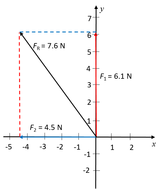
- Sketch the resultant of the following force vectors using the tail-to-tail method:
- [latex]\scriptsize \overrightarrow{{{{F}_{1}}}}=6.1\text{ N}[/latex] in the positive y-direction
- [latex]\scriptsize \overrightarrow{{{{F}_{2}}}}=4.5\text{ N}[/latex] in the negative x-direction
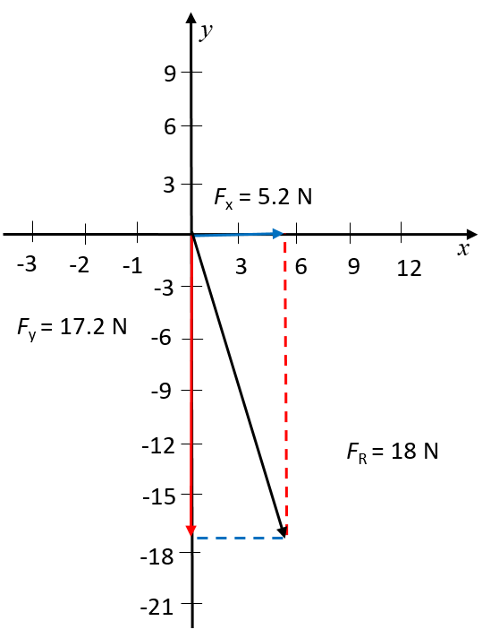
- Sketch the resultant of the following force vectors using the tail-to-tail method by first determining the resultant in the x- and y-directions:
- [latex]\scriptsize \overrightarrow{{{{F}_{1}}}}=2.3\text{ N}[/latex] in the positive y-direction
- [latex]\scriptsize \overrightarrow{{{{F}_{2}}}}=11.8\text{ N}[/latex] in the negative y-direction
- [latex]\scriptsize \overrightarrow{{{{F}_{3}}}}=7.7\text{ N}[/latex] in the negative y-direction
- [latex]\scriptsize \overrightarrow{{{{F}_{4}}}}=5.2\text{ N}[/latex] in the negative x-direction
- Draw sketch diagrams to show how you would determine the resultant force for the concurrent forces in the following cases. The diagrams do not have to be to scale.
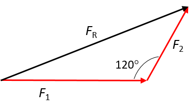
- [latex]\scriptsize \overrightarrow{{{{F}_{1}}}}=150\text{ N}[/latex] directly east and [latex]\scriptsize \overrightarrow{{{{F}_{2}}}}=90\text{ N}[/latex] at [latex]\scriptsize 60^\circ[/latex] north of east. Use the tail-to-head method.
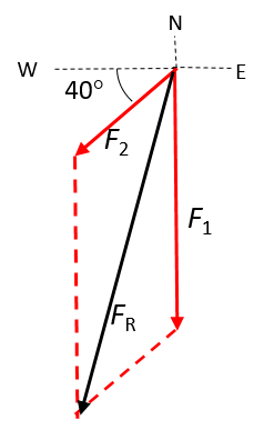
- [latex]\scriptsize \overrightarrow{{{{F}_{1}}}}=240\text{ N}[/latex] south and [latex]\scriptsize \overrightarrow{{{{F}_{2}}}}=120\text{ N}[/latex] at [latex]\scriptsize 40^\circ[/latex] south of west. Use the tail-to-tail method.
The full solutions can be found at the end of the unit.
Unit 1: Solutions
Exercise 1.1
- Because force is a vector, you have to state both a magnitude and a direction to describe a force. The unit for force is newtons (N).
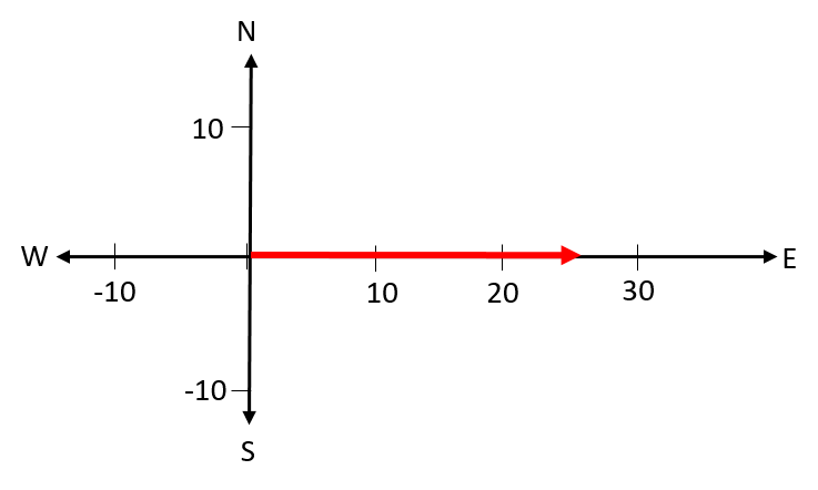
- [latex]\scriptsize 25\text{ }\text{N}[/latex] east
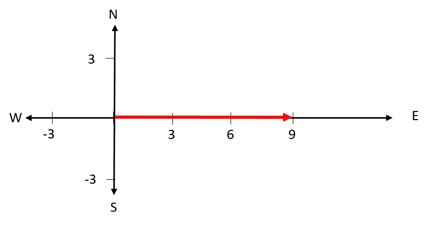
- [latex]\scriptsize \overrightarrow{{{{F}_{1}}}}=9\text{ }\text{N}[/latex] east; [latex]\scriptsize \overrightarrow{{{{F}_{2}}}}=6\text{ }\text{N}[/latex] south-east
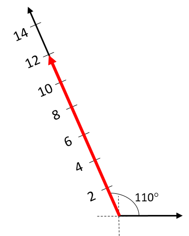
- [latex]\scriptsize \text{12 }\text{N, 20}^\circ[/latex] west of north.
- .
- The statement is false. The simple arithmetic sum can be used only if the two forces act in the same line (that is, one dimension). When the two forces act in different dimensions, the magnitude of the resultant will be smaller than the simple arithmetic sum of the two.
- The statement is false. When two concurrent forces act at right angles, the angle of the resultant will be smaller than [latex]\scriptsize 90^\circ[/latex]. If the two forces have equal magnitudes, the angle of the resultant will be [latex]\scriptsize 45^\circ[/latex]. If the force in the vertical direction is the larger of the two, the angle will be [latex]\scriptsize \gt 45^\circ[/latex]; if the force in the horizontal direction is the larger of the two, the angle will be [latex]\scriptsize \lt 45^\circ[/latex].
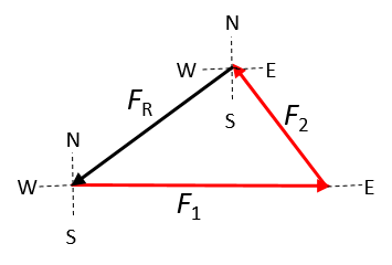
- The statement is false. The resultant force will be north of east. This can be seen on a vector diagram:
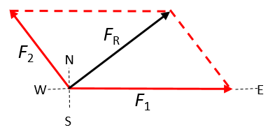
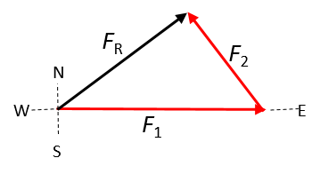
OR
The resultant has to be drawn from the same origin as the two applied forces. If the tail-to-head method is used, the resultant has to be drawn from the tail of the first arrow to the head of the second arrow; it is incorrect to draw it from the head of the second arrow to the tail of the first.
Correct:
Incorrect:
- Vector diagrams drawn with both the parallelogram and tail-to-head method are shown:
- When the angle between the two forces is [latex]\scriptsize 70^\circ[/latex]:
- When the angle between the two forces is [latex]\scriptsize 90^\circ[/latex]:
- When the angle between the two forces is [latex]\scriptsize 150^\circ[/latex]:
- When the angle between the two forces is [latex]\scriptsize 70^\circ[/latex]:
Unit 1: Assessment
- We define upwards as the positive y-direction and to the right as the positive x-direction.
- There are three forces acting in the y-direction. Because they act in one dimension, we can determine the resultant force as the simple arithmetic sum: [latex]\scriptsize 2.5\text{ N}[/latex], which means [latex]\scriptsize 2.5\text{ N}[/latex] upwards. The perpendicular force (in the horizontal direction) is [latex]\scriptsize 6.3\text{ N}[/latex] to the left.
- We define upwards as the positive y-direction and to the right as the positive x-direction.
- There are three forces acting in the y-direction. Because they act in one dimension, we can determine the resultant force in the y-direction as the simple arithmetic sum: [latex]\scriptsize -17.2\text{ N}[/latex], which means [latex]\scriptsize 17.2\text{ N}[/latex] downwards. The perpendicular force, in the horizontal direction, is [latex]\scriptsize 5.2\text{ N}[/latex] to the right.
- .
- .
- .
- .
Media Attributions
- PS 3_2.2_1_Img01_vector © DHET is licensed under a CC BY (Attribution) license
- PS 3_2.2_1_Img02_Example 1.1 © DHET is licensed under a CC BY (Attribution) license
- PS 3_2.2_1_Img03a_Example 1.2_1 © DHET is licensed under a CC BY (Attribution) license
- PS 3_2.2_1_Img03b_Example 1.2_2 © DHET is licensed under a CC BY (Attribution) license
- PS 3_2.2_1_Img04a_Example 1.3_1 © DHET is licensed under a CC BY (Attribution) license
- PS 3_2.2_1_Img04b_Example 1.3_2 © DHET is licensed under a CC BY (Attribution) license
- PS 3_2.2_1_Img04c_Example 1.3_3 © DHET is licensed under a CC BY (Attribution) license
- PS 3_2.2_1_Img05_Activity 1.1_1 © DHET is licensed under a CC BY (Attribution) license
- PS 3_2.2_1_Img06_Activity 1.1_2 © DHET is licensed under a CC BY (Attribution) license
- PS 3_2.2_1_Img07_Activity 1.1_3 © DHET is licensed under a CC BY (Attribution) license
- PS 3_2.2_1_Img08_Activity 1.1_5a © DHET is licensed under a CC BY (Attribution) license
- PS 3_2.2_1_Img09_Activity 1.1_5b © DHET is licensed under a CC BY (Attribution) license
- PS 3_2.2_1_Img10_Activity 1.1_5c © DHET is licensed under a CC BY (Attribution) license
- PS 3_2.2_1_Img11_Activity 1.1_discussion1 © DHET is licensed under a CC BY (Attribution) license
- PS 3_2.2_1_Img12_Activity 1.1_discussion2 © DHET is licensed under a CC BY (Attribution) license
- PS 3_2.2_1_Img13_Activity 1.1_discussion3 © DHET is licensed under a CC BY (Attribution) license
- PS 3_2.2_1_Img14_Activity 1.2_discussion1 © DHET is licensed under a CC BY (Attribution) license
- PS 3_2.2_1_Img15_Activity 1.2_discussion2 © DHET is licensed under a CC BY (Attribution) license
- PS 3_2.2_1_Img16_Activity 1.2_discussion3 © DHET is licensed under a CC BY (Attribution) license
- PS 3_2.2_1_Img17_Activity 1.2_discussion4 © DHET is licensed under a CC BY (Attribution) license
- PS 3_2.2_1_Img18_Exercise1.1_Q1a © DHET is licensed under a CC BY (Attribution) license
- PS 3_2.2_1_Img19_Exercise1.1_Q1b © DHET is licensed under a CC BY (Attribution) license
- PS 3_2.2_1_Img20_Exercise1.1_Q1c © DHET is licensed under a CC BY (Attribution) license
- PS 3_2.2_1_Img21_Exercise1.1_Q2c_answer © DHET is licensed under a CC BY (Attribution) license
- PS 3_2.2_1_Img22_Exercise1.1_Q2c_answer © DHET is licensed under a CC BY (Attribution) license
- PS 3_2.2_1_Img23_Exercise1.1_Q2c_answer © DHET is licensed under a CC BY (Attribution) license
- PS 3_2.2_1_Img24a_Exercise1.1_Q3a_answer © DHET is licensed under a CC BY (Attribution) license
- PS 3_2.2_1_Img24b_Exercise1.1_Q3a_answer © DHET is licensed under a CC BY (Attribution) license
- PS 3_2.2_1_Img25a_Exercise1.1_Q3b_answer © DHET is licensed under a CC BY (Attribution) license
- PS 3_2.2_1_Img25b_Exercise1.1_Q3b_answer © DHET is licensed under a CC BY (Attribution) license
- PS 3_2.2_1_Img26a_Exercise1.1_Q3c_answer © DHET is licensed under a CC BY (Attribution) license
- PS 3_2.2_1_Img26b_Exercise1.1_Q3c_answer © DHET is licensed under a CC BY (Attribution) license
- PS 3_2.2_1_Img27_Assessment_Q1_answer © DHET is licensed under a CC BY (Attribution) license
- PS 3_2.2_1_Img28_Assessment_Q2_answer © DHET is licensed under a CC BY (Attribution) license
- PS 3_2.2_1_Img29_Assessment_Q3_answer © DHET is licensed under a CC BY (Attribution) license
- PS 3_2.2_1_Img30_Assessment_Q4_answer © DHET is licensed under a CC BY (Attribution) license
- PS 3_2.2_1_Img31_Assessment_Q5a_answer © DHET is licensed under a CC BY (Attribution) license
- PS 3_2.2_1_Img32_Assessment_Q5b_answer © DHET is licensed under a CC BY (Attribution) license
a physical quantity that has both magnitude and direction
forces that act simultaneously on a single point or object
the force that represents the net effect of all forces acting on an object
