Magnetism and electricity: State, analyse and apply principles in electromagnetism
Unit 1: Magnetic field around a conductor
Leigh Kleynhans
Unit outcomes
By the end of this unit you will be able to:
- Identify and draw diagrams of the magnetic field associated with current:
- in a long, straight, current-carrying conductor
- in a solenoid.
- Identify and describe the use of the magnetic field and its application in electromagnets.
- Identify the effect of the magnetic field on a charged particle in motion.
What you should know
Before you start this unit, make sure you can:
- Describe what a magnetic field is. You can refer to level 2, subject outcome 4.1, units 1 and 2 to revise this.
- Describe what electric current is. You can refer to level 2, subject outcome 4.3, unit 1 to revise this.
Introduction
Parts of the text in this unit were sourced from Siyavula Physical Science Gr 11 Learner’s Book, Chapter 11, released under a CC-BY licence.
Up to this point you have learnt about electricity and magnetism as separate concepts. In this unit you will learn about the relationship between them. This relationship is called .
You should recall that an electric current is the movement of charges through a conducting wire. The higher the value of the current, the higher the rate of movement of the charges through the wire. You should also recall that a magnetic field is formed around a permanent magnet, and when an object made of a magnetic material is brought into this space it will experience a force. In addition, you have learnt about the magnetic field around the earth. You used magnetic field lines to represent magnetic fields.
The magnetic field around a straight current-carrying conductor
A scientist called Han Oersted discovered that when current is flowing in a wire, a magnetic field is produced. Activity 1.1 explores this discovery.
Activity 1.1: Investigate the magnetic field around a current-carrying conductor
Time required: 5 minutes
What you need:
- internet access
What to do:
Watch the video on Hans Oersted’s experiment by scanning the QR code or following the link.
What did you find?
- When there is no current flowing in the wire, the compass needle remains still.
- As soon as there is a current flowing in the wire, the compass needle is deflected (turns).
- When you disconnect the battery or remove the wire, the compass needle returns to its original position.
- The shape of the magnetic field around a current-carrying conductor is circular.
- The direction of the magnetic field is determined by the direction in which the current is flowing.
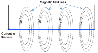
Oersted’s experiment demonstrated that there is a magnetic field that is formed when a current flows through a wire. This is shown graphically in figure 1.
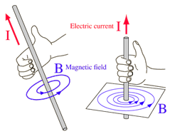
A simple rule to work out the direction of the magnetic field that is induced by the current is called the . With your thumb pointing in the direction of the current, curl the fingers of your right hand as if you are grabbing hold of the wire. Your curled fingers will be pointing in the direction of the magnetic field (see figure 2).
Note
When using the right-hand (thumb) rule, the thumb always points in the direction of . The flow of electrons would be in the opposite direction.
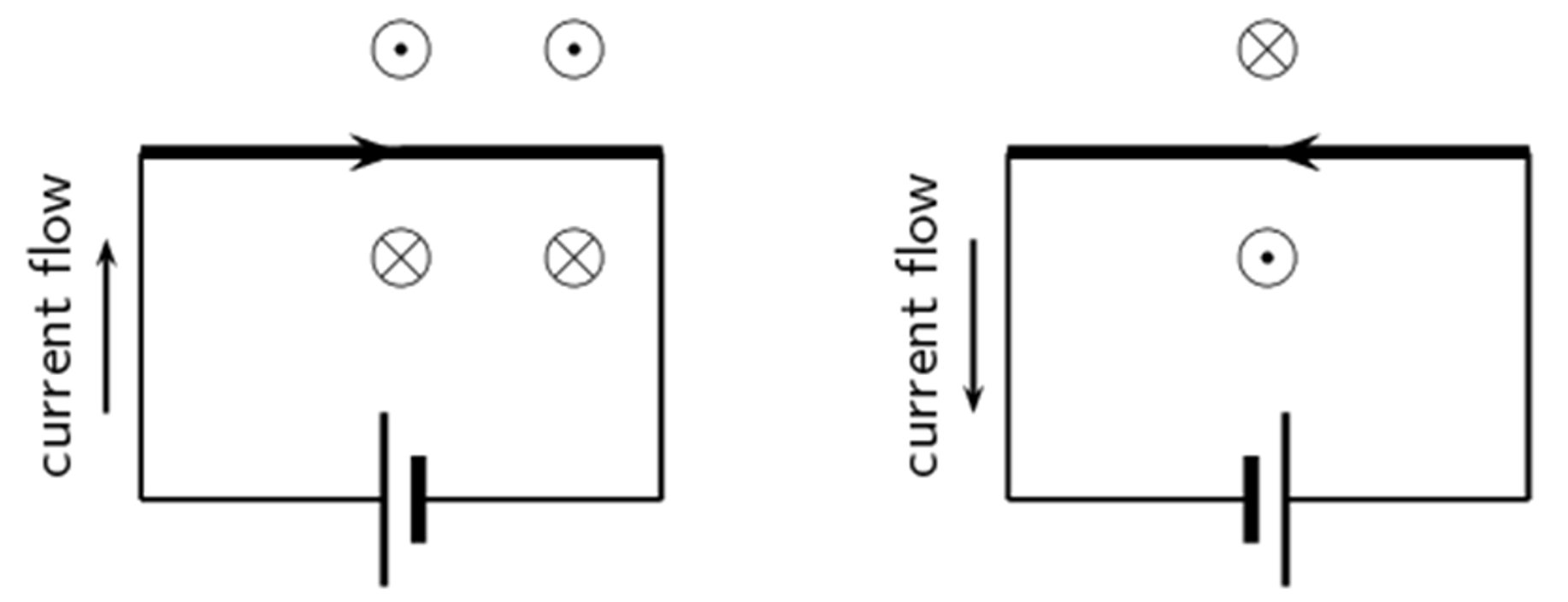
To make the drawing of these circular magnetic fields easier, we often refer to the wire as being perpendicular to the page. If the current is upwards, coming out of the page it is represented using a dot [latex]\scriptsize \odot[/latex]. A cross [latex]\scriptsize \otimes[/latex] can be used to show that the direction of the current is downward, going into the page. These symbols are used because, if you picture an arrow coming out of the page, you would see its sharp tip, which looks like a dot. If the arrow is going into the page, you would see the back of the arrow, which looks like a cross.
The use of this convention is illustrated in figure 3.

The direction of the magnetic field in (a) is described as anti-clockwise and in (b) as clockwise.
Field lines not only indicate direction of a field but also how strong the field is. In the magnetic field around a current-carrying conductor, the field will be strongest close to the conductor and gets weaker, the further away from the conductor. You will notice that the concentric circles in the diagrams get further apart to indicate this (as can be seen in figure 3 above).
The greater the value of the current in the wire, the stronger the magnetic field that will be produced around the wire. This can be indicated by drawing more concentric circles around a wire with a higher current.
The dot-cross notation can also be used for the direction of the magnetic field when the conductor is lying horizontal to the page. If the magnetic field direction is upwards, coming out of the page it is represented using a dot [latex]\scriptsize \odot[/latex] , and a cross [latex]\scriptsize \otimes[/latex] would indicate that the magnetic field is going into the page. When using the right-hand (thumb) rule in this situation, you start with curling your finger in the given direction of the magnetic field, and your thumb would point in the direction of conventional current flow. This is illustrated in figure 4.
Exercise 1.1
- Using dot-cross notation for the direction of current, draw the magnetic field around a current-carrying conductor that is perpendicular to the page and:
- the conventional current is going into the page. Describe the direction of the magnetic field.
- the conventional current is coming out of the page. Describe the direction of the magnetic field.
- Using dot-cross notation for the direction of the magnetic field, draw the magnetic field around a current-carrying conductor that is lying horizontally to the page and:
- the conventional current is to the right.
- the conventional current is to the left.
The full solutions are at the end of the unit.
Magnetic field around a solenoid
If you take a current-carrying wire and make a single loop with it, you can work out the pattern of the magnetic field around the loop. If you look at figure 5, on the left-hand diagram you can see the magnetic field around the loop shown using curved arrows, and in the diagram on the right, where the magnetic field is pointing out of the page it is shown using dots, and where it is pointing into the page It is shown with crosses.
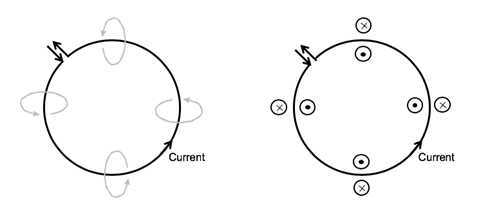
From the diagrams in figure 5, you can see that the magnetic field at the centre of the loop points outward from the page, and on the outside of the loop it points into the page. Again, you may use the right-hand (thumb) rule to work this out. If you curl your fingers in the direction of the magnetic field in a current-carrying loop, your thumb will point in the direction of the current in the loop. Or if you point your thumb in the direction of the current, your finger curl in the direction of the magnetic field.
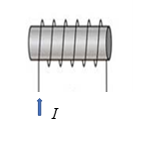
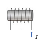
If you have several current-carrying loops, all wound in the same direction (like a spring), they form a . The magnetic fields from the individual loops in a solenoid have the same direction, so they work together to create a stronger magnetic field. Figure 6 shows what a magnetic field associated with a solenoid looks like.
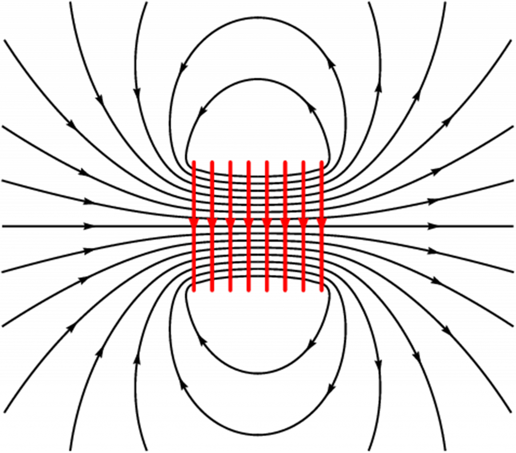
The magnetic field pattern around a solenoid is similar to the magnetic field pattern around a bar magnet which has a definite north and south pole. The magnetic field can be enhanced by placing a soft iron core through the centre of the solenoid. The magnetic field is only present when there is current in the solenoid and is referred to as an .
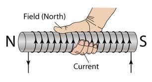
A variation on the right-hand rule will allow you to determine the poles of an electromagnet. If you make the fingers of your right hand follow the direction of the current in the loops, your thumb will point in the direction where the field lines emerge. This will be the north pole (where the field lines emerge from a bar magnet) and the opposite side would then be the south pole. We will refer to this rule as the .
Exercise 1.2
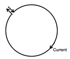
- The diagram below shows the direction of the current in a single looped wire.
- What is the direction of the magnetic field at the centre of the loop?
- What can you do to change the direction of the magnetic field so that it has the opposite direction?
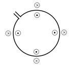
- The diagram below shows the direction of the magnetic field around a current-carrying looped conductor. What is in the direction of the current in the loop (clockwise or anti-clockwise)?
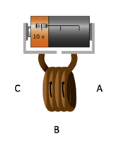
- Determine the polarity of the electromagnets (use left and right in your answer):
- .
- .
- .
The full solutions are at the end of the unit.
Activity 1.2: Investigate an electromagnet
Time required: 5 minutes
What you need:
- internet access
What to do:
- Go to the magnets and electromagnets simulation.
- When the simulation is running, click on the tab at the top of the window labelled ‘Electromagnet’.
- Move the compass around to see the direction of the magnetic field around the electromagnet.
- IMPORTANT NOTE: In this simulation the movement of charges shows the direction in which electrons would move, i.e. negative charges. Keep in mind that conventional current, which is the direction that you have been using for current (and when applying the right-hand rules), is opposite to the direction of electron movement.
- Turn the current on and off using the slider on the battery and note the direction of the magnetic field by moving the compass.
What did you find?
- When you move the slider on the battery so that current flows through the coil of wire, you observe that there is a magnetic field around the electromagnet (indicated by the deflection of the compass needle).
- As soon as the current is stopped, (by moving the slider on the battery to the centre) there is no longer a magnetic field (the compass points to the earth’s magnetic North in any position).
- Using the right-hand (solenoid) rule, confirms the polarity of the electromagnet as indicated by the compass needle.
Applications of electromagnets
The fact that the magnetism can be switched on and off in electromagnetics can be very useful. Electromagnets are commonly used in research, industry, medical, and consumer products. Examples of commonly used electromagnets are in electric bells, , loudspeakers, and scrapyard cranes.
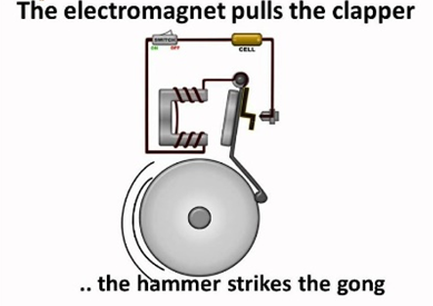
In an electric bell, shown in figure 8, when the switch is closed the electromagnet attracts the hammer, which then strikes the gong. The movement of the hammer breaks the circuit, so the magnetism disappears and the hammer springs back and completes the circuit again. The magnetism is then restored, and the hammer strikes the gong. This is repeated until the switch is turned off.
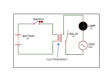
A relay switch is used as a safety mechanism so that a low voltage circuit can be used to close a high voltage circuit. In figure 9, when the switch in the [latex]\scriptsize 9\text{ V}[/latex] battery circuit is closed, the electromagnet closes the switch in the [latex]\scriptsize 230\text{ V}[/latex] circuit.
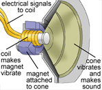
In a loudspeaker (see figure 10), to the electromagnet causes its polarity to keep on changing at regular intervals. The causes continuous attraction and repulsion to the permanent magnet which then causes the cone to vibrate and make sound.

To separate scrap metal from other junk in a scrapyard, a large electromagnet can be used (see figure 11). It is switched on to lift the metal, carried to another area and then switched off to release it.
Note
You can watch the following videos to see animations of the uses of electromagnets to consolidate your understanding:
Force on a charged particle in motion
We have seen that moving charge (current) has a magnetic field around it. If this charge moves in another magnetic field there will be interaction between the two fields. This interaction will result in a force being on exerted on the charge. If this flow of charge is in a wire, the entire wire will experience a force.
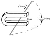
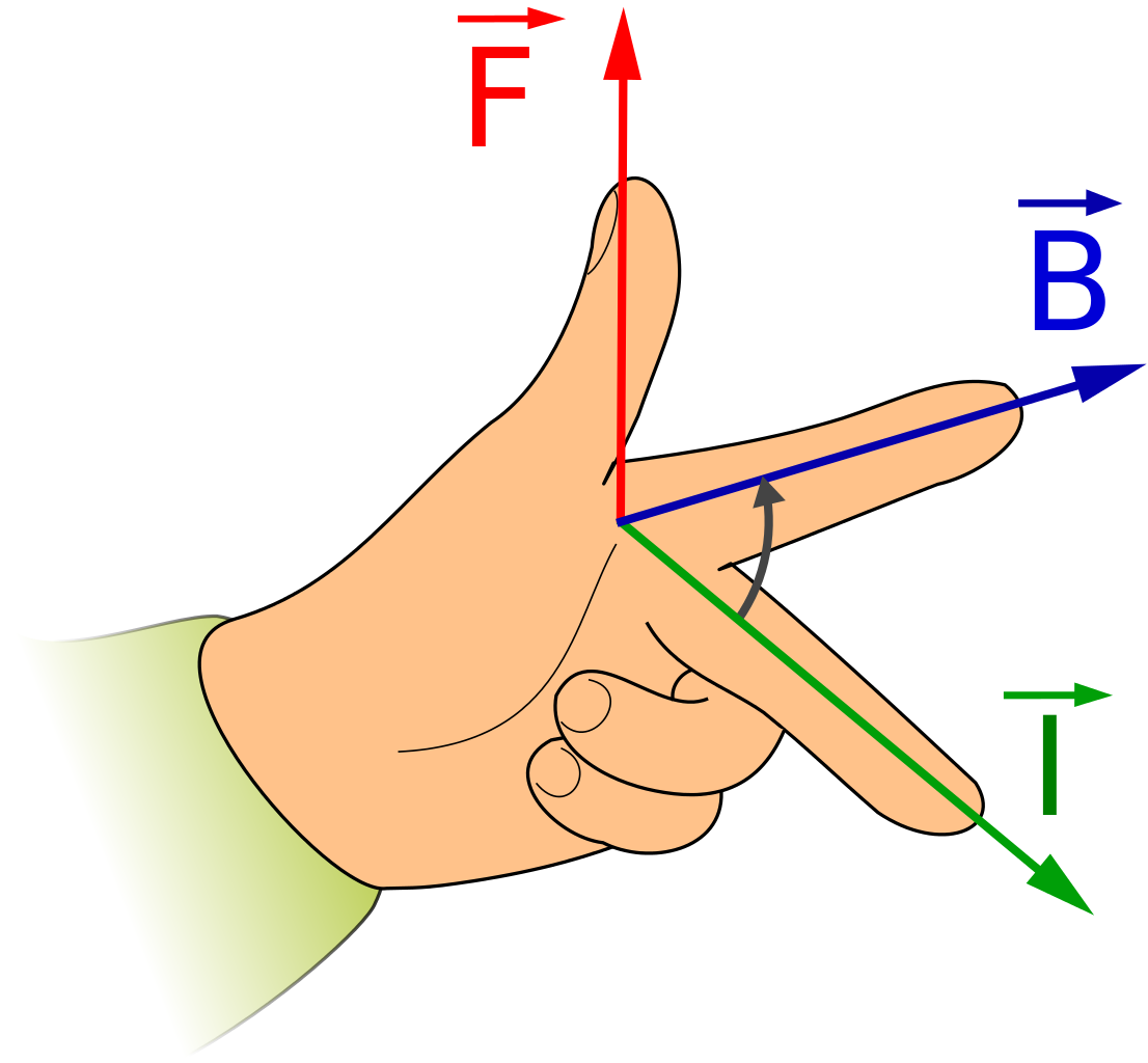
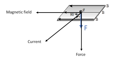
To determine the direction of the force, you can use your left hand to help you. Look at figure 13. With the index finger of your hand pointing in the direction of the magnetic field (B), and your middle finger pointing in the direction of the velocity of the charge (or in the direction of the current (I), your thumb will be pointing in the direction of the force (F). Your fingers must be held at right angles to each other. This is called the .
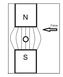
Exercise 1.3
- In the following diagram. B is the direction of the magnetic field, [latex]\scriptsize v[/latex] is the direction of movement of the positive charge [latex]\scriptsize q[/latex].
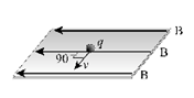
- What is the direction of the force on the positive charge shown in the diagram?
- What do you think the direction of the force would be on a negative charge moving in the same direction?
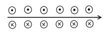
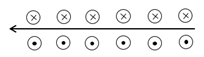
- Use the left-hand rule to fill in the missing directions of F, B or I on the following diagrams:
- .
- .
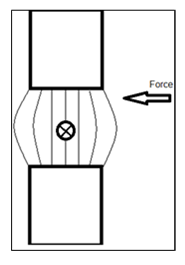
- .
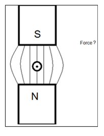
- .
The full solutions can be found at the end of the unit.
Summary
In this unit you have learnt the following:
- Moving charges (current) can create a magnetic field.
- The shape of the magnetic field around a current-carrying conductor is circular and the right-hand (thumb) rule can be used to determine the direction of the field.
- A solenoid is a current-carrying conductor folded into a series of loops and it creates a magnetic field similar to that of a bar magnet.
- An electromagnet can be made using a solenoid wrapped around a soft iron core to enhance the magnetic effect.
- The polarity of an electromagnet can be determined using the right-hand (solenoid) rule.
- Because the magnetism of an electromagnet can be switched on and off, it has useful applications in devices such as electric bells, relay switches, loudspeakers and scrapyard cranes.
- When the moving charged particles are placed at right angles into a magnetic field, a force is created.
- The direction of the force can be determined using the left-hand rule.
Unit 1: Assessment
Suggested time to complete: 20 minutes
- Describe how you could test for the presence of a magnetic field near a current-carrying conductor.
- The diagram below shows the direction of the current in a coil of conducting wire. What is the direction of the magnetic field at points A, B and C?
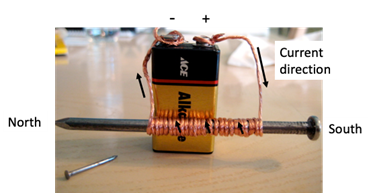
- An electromagnet is made by winding a length of current-carrying wire around a nail. The magnetic north is at the sharp tip of the nail. Draw a diagram of this set-up, showing how the wire should be connected to a torch cell to create a magnetic field in this direction.
- The diagram below shows the direction of the field lines of a circular magnetic field.
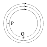
- What direction of current would create this magnetic field?
- How could the direction of the magnetic field be reversed?
- If a positive charge moves to the left at point P, what is the direction of the force on it?
- If a positive charge moves to the right at point Q, what is the force on it?
- If a compass is placed at point Q, what would happen to its needle?
- If the current is suddenly switched off, what would happen to the compass needle?
- Give three uses of electromagnets.
- Explain how an electromagnet could be used to separate iron filings from sand.
The full solutions can be found at the end of the unit.
Unit 1: Solutions
Exercise 1.1
- .
- clockwise

- anti-clockwise

- clockwise
- .
- .
- .
- .
Exercise 1.2
- .
- into the page (use the right-hand thumb rule)
- change the direction of the current to be anti-clockwise in the loop (the right-hand thumb rule)
- anti-clockwise (the magnetic field is coming out of the page in the centre of the loop – use the right-hand thumb rule)
- .
- North is left (the current is going up in front – use the right-hand solenoid rule – thumb points left)
- North is right (the current is going behind – use the right-hand solenoid rule – thumb points right)
Exercise 1.3
- .
- The force on the positive charge shown in the diagram is down. (Use the left-hand rule, where you move your hand so that the index finger points to the left, in the direction of the magnetic field, and the middle finger points out of the page, in the direction of the movement of the charge. Then the force on the charge is shown by the thumb, which is pointing downward.
- The force on a negative charge moving in this direction would mean conventional current (I) is going into the page. Use the left-hand rule to see that the force would therefore be in the opposite direction, so it would be up.
- The force on the positive charge shown in the diagram is down. (Use the left-hand rule, where you move your hand so that the index finger points to the left, in the direction of the magnetic field, and the middle finger points out of the page, in the direction of the movement of the charge. Then the force on the charge is shown by the thumb, which is pointing downward.
- (use the left-hand rule)
- I is into the page
- B is downwards
- F is left
Unit 1: Assessment
- You could test for the presence of a magnetic field using a compass. When a current is flowing in the wire, the compass needle will point in the direction of the magnetic field. You could also use pins or paper clips made from iron or some other magnetic metal. When a current is flowing in the wire, the paper clips will be attracted by the wire.
- Use the right-hand thumb rule – using your right hand, curl your fingers in the direction of the current in the wire, and then your thumb will point in the direction of the magnetic field (left). Therefore:
- At point A: direction of magnetic field is left.
- At point B: direction of magnetic field is right.
- At point C: direction of magnetic field is left.
- Your drawing should look similar to the picture shown below:
- .
- The current direction would be into the page.
- By reversing the current direction (i.e. out of the page).
- The force direction is into the page (you use the left-hand rule).
- No force, since it is moving parallel to the magnetic field.
- The compass needle would point to the left (in the direction of the magnetic field).
- It would point in the direction of the earth’s magnetic North.
- Electric bell, relay switch, loudspeaker, scrapyard crane.
- Turn the electromagnet on and pass it through the iron filings and sand mixture. The iron filings will be attracted to the magnet. Move the electromagnet to a separate container. Turn the electromagnet off and the iron filings will be released into the container.
Media Attributions
- img01_Figure1 © DHET is licensed under a CC BY (Attribution) license
- img02_Figure2 © DHET is licensed under a CC BY (Attribution) license
- img03_Figure3 © Siyavula is licensed under a CC BY-NC-ND (Attribution NonCommercial NoDerivatives) license
- img04_Figure4 © Siyavula is licensed under a CC BY-NC-ND (Attribution NonCommercial NoDerivatives) license
- img05_Figure5 © DHET is licensed under a CC BY (Attribution) license
- img06_Figure6 © Siyavula is licensed under a CC BY-NC-ND (Attribution NonCommercial NoDerivatives) license
- img07_Figure7 © L Kleynhans is licensed under a CC BY (Attribution) license
- img08_Ex1.2Q1b) © DHET is licensed under a CC BY (Attribution) license
- img09_Ex1.2Q2 © DHET is licensed under a CC BY (Attribution) license
- img10_Ex1.2Q3 © Siyavula is licensed under a CC BY-NC-ND (Attribution NonCommercial NoDerivatives) license
- img10_Ex1.2Q3 © Siyavula is licensed under a CC BY-NC-ND (Attribution NonCommercial NoDerivatives) license
- img11_Figure8 © L Kleynhans is licensed under a CC BY (Attribution) license
- img12_Figure9 © L Kleynhans is licensed under a CC BY (Attribution) license
- img13_Figure10 © L Kleynhans is licensed under a CC BY (Attribution) license
- img14_Figure11 © Pixabay is licensed under a CC0 (Creative Commons Zero) license
- img15_Figure12 © L Kleynhans is licensed under a CC BY (Attribution) license
- img16_Figure13 © Jfmelero is licensed under a CC BY-SA (Attribution ShareAlike) license
- img17_Ex1.3Q1 © DHET is licensed under a CC BY (Attribution) license
- img18_Ex1.3Q2 © L Kleynhans is licensed under a CC BY (Attribution) license
- img18_Ex1.3Q2 © L Kleynhans is licensed under a CC BY (Attribution) license
- img18_Ex1.3Q2 © L Kleynhans is licensed under a CC BY (Attribution) license
- img19_AssessmentQ2 © DHET is licensed under a CC BY (Attribution) license
- img20_AssessmentQ4 © DHET is licensed under a CC BY (Attribution) license
- img21_Ex1.1Q1a)answer © Siyavula is licensed under a CC BY-NC-ND (Attribution NonCommercial NoDerivatives) license
- img22_Ex.1.1.Q1b)answer © Siyavula is licensed under a CC BY-NC-ND (Attribution NonCommercial NoDerivatives) license
- img23_Ex. 1.1Q2a)answer © DHET is licensed under a CC BY (Attribution) license
- img24_Ex.1.1Q2b)answer © DHET is licensed under a CC BY (Attribution) license
- img25_Ex.1.3Q1a)answer © DHET is licensed under a CC BY (Attribution) license
- img26_AssessmentQ3answer © DHET is licensed under a CC BY (Attribution) license
the study of forces and magnetic fields associated with moving charges
a rule used to find the direction of the magnetic field around a current-carrying conductor – when the thumb of your right hand points in the direction of the current, your fingers curl in the direction of the magnetic field
the flow of positive charge from the positive terminal of a battery to the negative terminal
a series of loops of wire (like a spring)
a magnet made using a solenoid surrounding a soft iron core where the magnetism is only present when current is flowing in the solenoid
a rule used to find the north pole of an electromagnet – if you curl the fingers of your right hand in the direction of the current, then your thumb will point to north
systems used as a safety mechanism so that a low voltage circuit can be used to close a high voltage circuit
a current that changes direction at regular intervals (the type that is generated in power stations)
a rule used to find the direction of the force created when a current-carrying conductor is placed in the magnetic field of a permanent magnet – the thumb, index and middle finger of a left hand must be positioned at right-angles to each other, the thumb will give the direction of the force, the index finger the direction of the magnetic field (towards the south) and the middle finger the direction of the current
