Magnetism and electricity: State, analyse and apply principles of static electricity (electrostatics)
Unit 2: Electric fields
Leigh Kleynhans
Unit outcomes
By the end of this unit you will be able to:
- Identify and draw the electric field around:
- single charges
- a pair of charges
- a Faraday cage.
- Calculate electric field strength:
- around a charge
- between parallel plates.
What you should know
Before you start this unit, make sure you can:
- Describe how objects become charged. You can refer to level 2, subject outcome 4.2, unit 1 to revise this. [link to Physical Science Level 2, Subject Outcome 4.2, Unit 1]
- Explain that a charged object can exert a force on other charged objects. You can refer to level 3, subject outcome 4.1, unit 1 to revise this. [link to Physical Science Level 3, Subject Outcome 4.1, Unit 1]
Introduction
Parts of the text in this unit were sourced from Siyavula Physical Science Gr 11 Learner’s Book, Chapter 9, released under a CC-BY licence.
You have learnt that charged objects can exert forces of attraction or repulsion on one another without needing to touch each other. This is because any charged object creates an in the space around it, and any other object that moves into this space experiences the effects of this electric field.
The electric field is described as a region in which an electric charge experiences a force. In this unit, you will learn how to draw the electric field using electric field lines, and how to find the magnitude and direction of the electric field.
Electric fields
We have seen in the previous unit that point charges exert forces on each other even when they are far apart and not touching each other. How do the charges ‘know’ about the existence of other charges around them?
The answer is that every charge is surrounded in space by an invisible electric field. The electric field is the region of space in which another electric charge will experience a force. An electric field is a vector. The direction of an electric field at a point in space is the same direction in which a would move if placed at that point.
Note
Watch this animation, called Electrostatics explained – part 1, by cg-physics-global, which gives a visual representation of an electric field.
Representing electric fields
It is useful to use diagrams to indicate these invisible electric fields. These diagrams use to indicate the characteristics of the electric field.
We use the following conventions when drawing electric field lines:
- Arrows on the field lines indicate the direction of the field, i.e. the direction in which a positive test charge would move if placed in the field.
- Electric field lines therefore point away from positive charges (like charges repel) and towards negative charges (unlike charges attract).
- Field lines are drawn closer together where the field is stronger.
- Field lines do not touch or cross each other.
- Field lines are drawn perpendicular to a charge or charged surface.
Look at the diagrams below which are representations of electric fields around a positive charge and a negative charge.
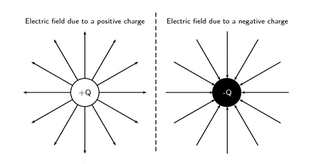
The field lines go outwards from a positive fixed charge, as this is the direction a positive test charge would move if placed in the field (repulsion). The field lines go inwards around a negative fixed charge, as this is the direction in which a positive test charge will move if placed in the field (attraction).
Close to the central charges, the field lines are close together. This is where the electric field is strongest. Further away from the central charges, where the electric field is weaker, the field lines are more spread out from each other.
The greater the magnitude of the charge, the stronger its electric field. We represent this by drawing more field lines around the greater charge than around charges with smaller magnitudes.

Some important points to remember about electric fields:
- There is an electric field at every point in space surrounding a charge.
- Field lines are merely a representation – they are not real. When we draw them, we just pick convenient places to indicate the field in space.
- Field lines exist in three dimensions, not only in two dimensions as we draw them.
- The number of field lines we draw is proportional to the charge.
Resultant electric fields around pairs of charges
When two charges are placed in the same area, their electric fields will interact. When a positive test charge is placed in the field, the force it experiences will be the resultant of the forces experienced from each individual field.
The diagram below represents the resultant electric field around two positive charges.

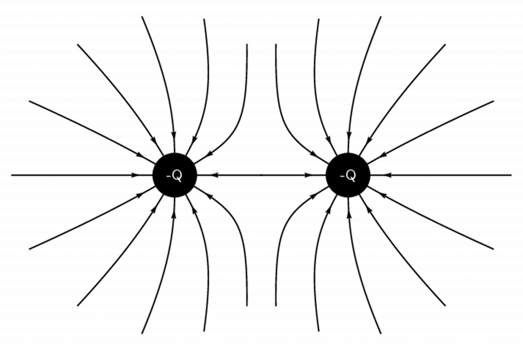
The diagram representing the resultant electric field around two negative charges will be the same as the diagram above, except the arrowheads will go inwards.
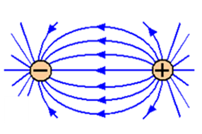
When one negative charge and one positive charge have interacting electric fields, a positive test charge will be attracted towards the negative fixed charge and repelled by the positive fixed charge. The resulting electric field is shown in Figure 4 below.
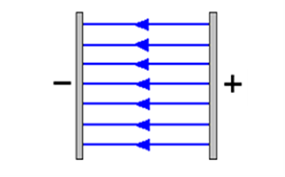
Electric field around charged parallel plates
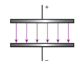
Electric fields can also develop between two metal plates when they are connected to a power source. The one plate will be positively charged and the other plate will be negatively charged.
The electric field around point or spherical charges is described as a . The strength of the field decreases as the distance from the central charge increases. This can be seen in the field diagrams by noting that the field lines get further apart.
The electric field between parallel plates is described as being a . The strength of the field is the same at any point between the plates. This can be seen in the field diagrams by noting that the field lines are parallel.
Electric field around a Faraday cage
A Faraday cage is a hollow structure made from a conducting material. An external electrical field causes the electric charges within the cage’s conducting material to be distributed so that they cancel the field’s effect in the cage’s interior.

This phenomenon is used to protect sensitive electronic equipment often during testing or alignment of the device. They are also used to protect people and equipment against actual electric currents such as lightning strikes and electrostatic discharges, since the enclosing cage conducts current around the outside of the enclosed space and none passes through the interior. This was discussed in level 2 subject outcome 4.2 unit 2 on interaction of charge.
Activity 2.1: Use an internet simulation to observe the electric field around positive and negative charges
Suggested time: 10 minutes
What you need:
- internet access
What to do:
- Go to the Charges and Fields simulation.
- When the window opens with the simulation, at the bottom of the screen you will see a red positive charge (labelled [latex]\scriptsize +1\text{ nC}[/latex]) and a blue negative charge (labelled [latex]\scriptsize -1\text{ nC}[/latex]). Drag the positive charge into the middle of the screen. (You can do this by drag and drop i.e., select the charge by clicking on it, move it while holding down the mouse button, then let go of the mouse button when the charge is in the middle of the screen.)
- As soon as you have positioned the charge in the middle of the screen you will notice the electric field arrows around it. The brightness of the field arrows indicate the strength of the electric field at that point.
- Notice the direction in which the electric field arrows are pointing.
- Notice the brightness of the field arrows further away from the charge. What does this tell you about the strength of the electric field near the charge compared with further away from the charge?
- Click the ‘Reset’ button on the bottom right of the screen (↺), and now drag the negative charge into the middle of the screen. Are the field arrows pointing in the direction that you expect them to?
- Now reset all the settings and add one positive and one negative charge to the window. Notice the shape of the electric field that forms around these charges.
- Now reset all the settings and add two positive charges to the window. Notice the shape of the electric field that forms around these charges.
- Now reset all the settings and add two negative charges to the window. Notice the shape of the electric field that forms around these charges.
What did you find?
This simulation shows that the direction of the electric field points outward from a positive charge, and inward towards a negative charge. When two charges are close to each other, the electric fields combine to form a field pattern which depends on the types of the charges.
The simulation should have confirmed your understanding of the shape of electric fields around single charges and pairs of charges as discussed in this unit. You will also have confirmed that the field is strongest close to the source of the field and gets weaker as you move further away from the charge.
Calculating electric field strength around a point charge ([latex]\scriptsize Q[/latex])
In activity 2.1 you would have noticed that the electric field is strongest nearer the charge and becomes weaker the further out you go from the charge.
To calculate the of the electric field at a distance [latex]\scriptsize r[/latex] from a charge [latex]\scriptsize Q[/latex] , you can use the equation: [latex]\scriptsize E=\displaystyle \frac{{kQ}}{{{{r}^{2}}}}[/latex]
Where:
[latex]\scriptsize E[/latex] is the magnitude of the electric field strength, measured in units of [latex]\scriptsize \text{N}\text{.}{{\text{C}}^{{\text{-1}}}}[/latex]
[latex]\scriptsize k[/latex] is the electrostatic constant: [latex]\scriptsize k=9\text{ x 1}{{\text{0}}^{9}}\text{ }{{\text{N}}^{2}}.{{\text{m}}^{2}}.{{\text{C}}^{{-2}}}[/latex]
[latex]\scriptsize Q[/latex] is the magnitude of the charge that creates the field, measured in coulombs (C)
[latex]\scriptsize r[/latex] is the distance from the charge, measured in metres (m).
In this equation you can see that the electric field is proportional to [latex]\scriptsize \displaystyle \frac{1}{{{{r}^{2}}}}[/latex]. In other words, the greater the distance away from the charge, the weaker the electric field. This supports your observations of the reduced strength of the electric field further away from the charge in activity 2.1.
Note
This formula can only be used for calculations involving point charges or hollow spheres. It cannot be used for parallel plates.
Example 2.1
What is the electric field strength at a point that is [latex]\scriptsize 3\text{ mm}[/latex] to the right of a charge [latex]\scriptsize Q=-2\text{ nC}[/latex]?
Solution
Step 1: Write down the given information, check units and convert if necessary
[latex]\scriptsize \begin{align*}r&=3\text{ mm = 0}\text{.003 m}\\Q&=-2\text{ nC = 2 x 1}{{\text{0}}^{{-9}}}\text{ C}\\E&=?\end{align*}[/latex]
Step 2: Write down the formula
[latex]\scriptsize E=\displaystyle \frac{{kQ}}{{{{r}^{2}}}}[/latex]
Step 3: Substitute the values into the formula and calculate the answer
[latex]\scriptsize \displaystyle \frac{{(9\text{ x 1}{{\text{0}}^{9}})(2\text{ x 1}{{\text{0}}^{{-9}}})}}{{{{{0.003}}^{2}}}}\text{ = 2 x 1}{{\text{0}}^{6}}\text{ N}\text{.}{{\text{C}}^{{-1}}}[/latex]
Step 4: Work out the direction of the electric field
The source of the field is a negative charge, so the direction of the electric field will be towards [latex]\scriptsize Q[/latex]. Therefore the direction at a point to the right of [latex]\scriptsize Q[/latex] will be to the left.
Step 5: Write the final answer with magnitude and direction
[latex]\scriptsize \text{2 x 1}{{\text{0}}^{6}}\text{ N}\text{.}{{\text{C}}^{{-1}}}[/latex] to the left
Exercise 2.1
- Calculate the electric field strength at a point [latex]\scriptsize 0.3\text{ m}[/latex] to the left of a point charge of [latex]\scriptsize 6\text{ x 1}{{\text{0}}^{8}}\text{ C}[/latex].
- If the electric field strength is [latex]\scriptsize 25\text{ N}\text{.}{{\text{C}}^{{-1}}}[/latex] to the right at a distance of [latex]\scriptsize 5\text{ cm}[/latex] to the left of a charge [latex]\scriptsize Q[/latex], calculate the charge on [latex]\scriptsize Q[/latex].
- At what distance will the electric field strength be [latex]\scriptsize 2\text{ x 1}{{\text{0}}^{6}}\text{ N}\text{.}{{\text{C}}^{{-1}}}[/latex] outwards from a charge of [latex]\scriptsize 70\text{ nC}[/latex]?
The full solutions are at the end of the unit.
Calculating the force experienced by a test charge ([latex]\scriptsize q[/latex]) placed in an electric field
When a test charge ([latex]\scriptsize q[/latex]) is placed in an electric field, it will experience a force (according to Coulomb’s law). The following formula can be used to calculate the force if the charge on the source of the field ([latex]\scriptsize Q[/latex]) is not known but the electric field strength ([latex]\scriptsize E[/latex]) is known.
[latex]\scriptsize F=Eq[/latex] or [latex]\scriptsize E=\displaystyle \frac{F}{q}[/latex]
Where:
[latex]\scriptsize F[/latex] is the force measured in [latex]\scriptsize \text{N}[/latex]
[latex]\scriptsize E[/latex] is the electric field strength measured in [latex]\scriptsize \text{N}\text{.}{{\text{C}}^{{-1}}}[/latex]
[latex]\scriptsize q[/latex] is the charge on the test charge measured in [latex]\scriptsize \text{C}[/latex]
Note
This formula can be used for calculations involving point charges or hollow spheres and for parallel plates.
Example 2.2
Calculate the magnitude of the force experienced by a charge of [latex]\scriptsize 3\text{ }\mu \text{C}[/latex] placed in an electric field with a strength of [latex]\scriptsize 4\text{ x 1}{{\text{0}}^{3}}\text{ N}\text{.}{{\text{C}}^{{-1}}}[/latex].
Solution
Step 1: Write down the given information, check units and convert if necessary
[latex]\scriptsize \begin{align*}q&=3\text{ }\mu \text{C = 3 x1}{{\text{0}}^{{-6}}}\text{ C}\\E&=4\text{ x 1}{{\text{0}}^{3}}\text{ N}\text{.}{{\text{C}}^{{-1}}}\\F&=?\end{align*}[/latex]
Step 2: Write down the formula
[latex]\scriptsize F=Eq[/latex]
Step 3: Substitute values and calculate answer
[latex]\scriptsize (4\text{ x 1}{{\text{0}}^{3}})(3\text{ x 1}{{\text{0}}^{{-6}}})=\text{ 0}\text{.012 N}[/latex]
The question asks for the magnitude of the force, so no direction required.
Exercise 2.2
- Calculate the magnitude of the force on a charge of [latex]\scriptsize 26\text{ C}[/latex] placed in an electric field of strength [latex]\scriptsize 60\text{ N}\text{.}{{\text{C}}^{{-1}}}[/latex].
- What is the magnitude of the electric field strength if a charge of [latex]\scriptsize 250\text{ mC}[/latex] experiences a force of [latex]\scriptsize 35\text{ N}[/latex] when placed in the field?
- What is the magnitude of a charge if it experiences of force of [latex]\scriptsize 2\text{ N}[/latex] when placed in an electric field of strength [latex]\scriptsize 560\text{ N}\text{.}{{\text{C}}^{{-1}}}[/latex]?
The full solutions are at the end of the unit.
Note
By convention, the symbol [latex]\scriptsize Q[/latex] is used for the charge that is the source of the field and the symbol [latex]\scriptsize q[/latex] is used for a charge that is placed in the field.
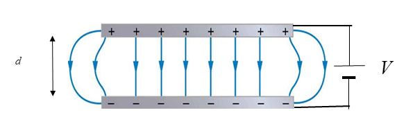
Calculating the electric field strength between parallel plates
The electric field strength between parallel plates is determined by the voltage connected to the plates and the distance between the plates. The greater the voltage, the stronger the electric field. The further apart the plates, the weaker the electric field. The formula to calculate the electric field strength between parallel plates is:
[latex]\scriptsize E=\displaystyle \frac{V}{d}[/latex]
Where:
[latex]\scriptsize E[/latex] is the electric field strength in [latex]\scriptsize \text{N}\text{.}{{\text{C}}^{{-1}}}[/latex]
[latex]\scriptsize V[/latex] is the voltage measured in volts ([latex]\scriptsize V[/latex])
[latex]\scriptsize d[/latex] is the distance between the plates measured in metres ([latex]\scriptsize m[/latex])
Note
This formula can only be used for the electric field strength between parallel plates.
Example 2.3
Calculate the electric field strength between two parallel plates when the voltage is [latex]\scriptsize 6\text{ V}[/latex] and the distance between the plates is [latex]\scriptsize 4\text{ cm}[/latex].
Solution
Step 1: Write down the given information, check the units and convert if required
[latex]\scriptsize \begin{align*}V&=6\text{ V}\\d&=\text{4 cm = 0}\text{.04 m}\\E&=?\end{align*}[/latex]
Step 2: Write down the formula
[latex]\scriptsize E=\displaystyle \frac{V}{d}[/latex]
Step 3: Substitute the values and calculate the answer
[latex]\scriptsize \displaystyle \frac{6}{{0.04}}=\text{ 150 N}\text{.}{{\text{C}}^{{-1}}}[/latex]
Step 4: Determine the direction of the field
Rule: the direction of the field is the direction in which a positive test charge will move. A positive test charge will move towards the negative plate.
Step 5: Write answer
[latex]\scriptsize 150\text{ N}\text{.}{{\text{C}}^{{-1}}}[/latex] towards the negative plate
Exercise 2.3
- Calculate the strength of the electric field between two parallel plates if they are [latex]\scriptsize 2\text{ m }[/latex] apart and the voltage is [latex]\scriptsize 24\text{ V}\text{.}[/latex]
- If the electric field strength between two parallel plates is [latex]\scriptsize 2\text{ x 1}{{\text{0}}^{4}}\text{ N}\text{.}{{\text{C}}^{{-1}}}[/latex] and the voltage is [latex]\scriptsize 220\text{ V}[/latex], calculate the distance between the plates.
The full solutions are at the end of the unit.
Summary
In this unit you have learnt the following:
- An electric field is a region of space in which an electric charge will experience a force.
- The direction of a field at a point in space is the direction in which a positive test charge would move if placed at that point.
- We can represent an electric field using field lines.
- An electric field due to a point charge [latex]\scriptsize Q[/latex] is defined as the force per unit charge [latex]\scriptsize q[/latex] placed in the field.
- The magnitude of an electric field around a point charge can be calculated using the formulae: [latex]\scriptsize E=\displaystyle \frac{{kQ}}{{{{r}^{2}}}}[/latex] or [latex]\scriptsize E=\displaystyle \frac{F}{Q}[/latex].
- The magnitude of an electric field around parallel plates can be calculated using the formulae: [latex]\scriptsize E=\displaystyle \frac{F}{Q}[/latex] or [latex]\scriptsize E=\displaystyle \frac{V}{d}[/latex].
- The units of an electric field strength are newtons per coulomb ([latex]\scriptsize \text{N}\text{.}{{\text{C}}^{{-1}}}[/latex]).
Unit 2: Assessment
Suggested time to complete: 30 minutes
- Draw diagrams to illustrate the electric fields of the following:
- A negative point charge.
- Two negative charges near each other.
- Two oppositely charged parallel plates.
State whether the fields are radial or uniform.
- A charge of [latex]\scriptsize 6\text{ }\mu \text{C}[/latex] is placed in an electric field around a point charge of [latex]\scriptsize 8\text{ x 1}{{\text{0}}^{{-3}}}\text{ C}[/latex] in a position [latex]\scriptsize 7\text{ cm}[/latex] from the source of the field. Calculate the magnitude of the force it will experience.
- A charge of [latex]\scriptsize -3\text{ C}[/latex] is placed in an electric field between two parallel, oppositely charged plates with a voltage of [latex]\scriptsize 0.6\text{ V}[/latex] and experiences of force of [latex]\scriptsize 5\text{ N}[/latex]. Calculate the distance between the plates.
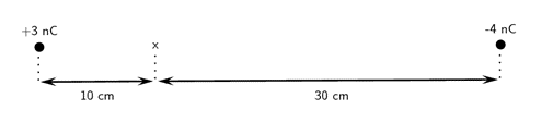
- Two charges of [latex]\scriptsize {{Q}_{1}}=+3\text{ nC}[/latex] and [latex]\scriptsize {{Q}_{2}}=-4\text{ nC}[/latex] are separated by a distance of [latex]\scriptsize 50\text{ cm}[/latex]. What is the electric field strength at a point that is [latex]\scriptsize 10\text{ cm}[/latex] from [latex]\scriptsize {{Q}_{1}}[/latex] and [latex]\scriptsize 30\text{ cm}[/latex] from [latex]\scriptsize {{Q}_{2}}[/latex]? The point lies at x in the diagram below.
- Two point charges form a right-angled triangle with the point [latex]\scriptsize A[/latex] at the origin. Their charges are [latex]\scriptsize {{Q}_{2}}=6\text{ nC}[/latex] and [latex]\scriptsize {{Q}_{3}}=-3\text{ nC}[/latex]. The distance between [latex]\scriptsize A[/latex] and [latex]\scriptsize {{Q}_{2}}[/latex] is [latex]\scriptsize 0.05\text{ m}[/latex] and the distance between [latex]\scriptsize A[/latex] and [latex]\scriptsize {{Q}_{3}}[/latex] is [latex]\scriptsize 0.03\text{ m}[/latex]. What is the net electric field measured at [latex]\scriptsize A[/latex] from the two charges if they are arranged as shown?

The full solutions are at the end of the unit.
Unit 2: Solutions
Exercise 2.1
- .
[latex]\scriptsize \begin{align*}r&=0.3\text{ m}\\Q&=\text{ 6 x 1}{{\text{0}}^{8}}\text{ C}\\E&=?\\E&=\displaystyle \frac{{kQ}}{{{{r}^{2}}}}\text{ = }\displaystyle \frac{{(9\text{ x 1}{{\text{0}}^{9}})(6\text{ x 1}{{\text{0}}^{{8)}}}}}{{{{{0.3}}^{2}}}}\text{ = 6 x 1}{{\text{0}}^{{19}}}\text{ N}\text{.}{{\text{C}}^{{-1}}}\text{ to the left}\end{align*}[/latex] - .
[latex]\scriptsize \begin{align*}r&=\text{ 5 cm = 0}\text{.05 m}\\E&=25\text{ N}\text{.}{{\text{C}}^{{-1}}}\\Q&=?\\E&=\displaystyle \frac{{kQ}}{{{{r}^{2}}}}\text{ }\\\text{25}&=\displaystyle \frac{{(9\text{ x 1}{{\text{0}}^{9}})Q}}{{{{{0.05}}^{2}}}}\\Q&=\text{6}\text{.94 x 1}{{\text{0}}^{{-12}}}\text{ C}\\Q&=-6.94\text{ x 1}{{\text{0}}^{{-12}}}\text{ C}\end{align*}[/latex]
The charge must be negative if the direction of field is towards the charge [latex]\scriptsize Q[/latex] - .
[latex]\scriptsize \begin{align*}Q&=\text{ 70 nC = 70 x 1}{{\text{0}}^{9}}\text{ C}\\E&=2\text{ x 1}{{\text{0}}^{6}}\text{ N}\text{.}{{\text{C}}^{{-1}}}\\r&=?\\E&=\displaystyle \frac{{kQ}}{{{{r}^{2}}}}\text{ }\\\text{2 x1}{{\text{0}}^{6}}&=\text{ }\displaystyle \frac{{(9\text{ x 1}{{\text{0}}^{9}})(70\text{ x 1}{{\text{0}}^{{-9}}})}}{{{{r}^{2}}}}\\r&=\text{ 0}\text{.018m}\end{align*}[/latex]
Exercise 2.2
- .
[latex]\scriptsize \begin{align*}q&=26\text{ C}\\E&=\text{60 N}\text{.}{{\text{C}}^{{-1}}}\\F&=?\\F&=Eq=60\text{ x 26 = 1 560 N}\end{align*}[/latex] - .
[latex]\scriptsize \begin{align*}q&=250\text{ mC = 0}\text{.25 C}\\F&=35\text{ N}\\E&=?\\E&=\displaystyle \frac{F}{q}\text{ = }\displaystyle \frac{{35}}{{0.25}}\text{ = 140 N}\text{.}{{\text{C}}^{{-1}}}\end{align*}[/latex] - .
[latex]\scriptsize \begin{align*}F&=2\text{ N}\\E&=560\text{ N}\text{.}{{\text{C}}^{{-1}}}\\q&=?\\E&=\displaystyle \frac{F}{q}\text{ }\\\text{560}&=\displaystyle \frac{2}{q}\text{ }\\\text{q}&=\text{3}\text{.57 x 1}{{\text{0}}^{{-3}}}\text{ C}\end{align*}[/latex]
Exercise 2.3
- .
[latex]\scriptsize \begin{align*}d&=2\text{ m}\\V&=24\text{ V}\\E&=\text{?}\\E&=\displaystyle \frac{V}{d}=\displaystyle \frac{{24}}{2}\text{ = 12 N}\text{.}{{\text{C}}^{{-1}}} && \text{towards negative plate}\end{align*}[/latex] - .
[latex]\scriptsize \displaystyle \begin{align*}V&=220\text{ V}\\E&=2\text{ x 1}{{\text{0}}^{4}}\text{ N}\text{.}{{\text{C}}^{{-1}}}\\d&=?\\E&=\displaystyle \frac{V}{d}\\2\text{ x 1}{{\text{0}}^{4}}&=\displaystyle \frac{{220}}{d}\text{ }\\d&=\text{0}\text{.011 m}\end{align*}[/latex]
Unit 2: Assessment
- .
- .

radial - .
radial - .
uniform
- .
- .
[latex]\scriptsize \begin{align*}Q&=8\text{ x 1}{{\text{0}}^{{-3}}}C\\q&=6\text{ }\mu \text{C = 6 x 1}{{\text{0}}^{{-6}}}\text{ C}\\r&=7\text{ cm = 0}\text{.07 m}\\F&=?\\E&=\displaystyle \frac{{kQ}}{{{{r}^{2}}}}=\displaystyle \frac{{(9\text{ x 1}{{\text{0}}^{9}})(8\text{ x 1}{{\text{0}}^{{-3}}})}}{{{{{0.07}}^{2}}}}=1.\text{47 x 1}{{\text{0}}^{{10}}}\text{ N}\text{.}{{\text{C}}^{{-1}}}\\F&=Eq=(1.47\text{ x 1}{{\text{0}}^{{10}}})(6\text{ x 1}{{\text{0}}^{{-6}}})=88\text{ 163,27 N}\end{align*}[/latex] - .
[latex]\scriptsize \begin{align*}q&=-3\text{ C}\\V&=0.6\text{ V}\\F&=5\text{ N}\\d&=?\\E&=\displaystyle \frac{F}{q}=\displaystyle \frac{5}{3}=1.67\text{ N}\text{.}{{\text{C}}^{{-1}}}\\E&=\displaystyle \frac{V}{d}\\1.67&=\displaystyle \frac{{0.6}}{d}\\d&=0.36\text{ m}\end{align*}[/latex] - First solve for [latex]\scriptsize {{Q}_{1}}[/latex]: [latex]\scriptsize \displaystyle E=\displaystyle \frac{{kQ}}{{{{r}^{2}}}}=\displaystyle \frac{{(9\text{ x 1}{{\text{0}}^{9}})(3\text{ x 1}{{\text{0}}^{{-9}}})}}{{{{{0.1}}^{2}}}}=2\text{ 700 N}\text{.}{{\text{C}}^{{-1}}}[/latex] to the right
.
Then solve for [latex]\scriptsize {{Q}_{2}}[/latex]: [latex]\scriptsize E=\displaystyle \frac{{kQ}}{{{{r}^{2}}}}=\displaystyle \frac{{(9\text{ x 1}{{\text{0}}^{9}})(4\text{ x 1}{{\text{0}}^{{-9}}})}}{{{{{0.3}}^{2}}}}=3.\text{99 x 1}{{\text{0}}^{2}}\text{ N}\text{.}{{\text{C}}^{{-1}}}[/latex] to the right
The field is away from [latex]\scriptsize {{Q}_{1}}[/latex] and towards [latex]\scriptsize {{Q}_{2}}[/latex]. We need to add the two electric fields because both are in the same direction.
[latex]\scriptsize {{E}_{{total}}}=\text{ 2 700 + 3}\text{.99 x 1}{{\text{0}}^{2}}=\text{ 3 099 N}\text{.}{{\text{C}}^{{-1}}} \text{ towards }{{Q}_{2}}[/latex] - First calculate field from [latex]\scriptsize {{Q}_{2}}[/latex]: [latex]\scriptsize E=\displaystyle \frac{{kQ}}{{{{r}^{2}}}}=\displaystyle \frac{{(9\text{ x 1}{{\text{0}}^{9}})(6\text{ x 1}{{\text{0}}^{{-9}}})}}{{{{{0.05}}^{2}}}}=2.\text{16 x 1}{{\text{0}}^{4}}\text{ N}\text{.}{{\text{C}}^{{-1}}}[/latex] to the left
Now calculate the field from [latex]\scriptsize {{Q}_{3}}[/latex]: [latex]\scriptsize E=\displaystyle \frac{{kQ}}{{{{r}^{2}}}}=\displaystyle \frac{{(9\text{ x 1}{{\text{0}}^{9}})(3\text{ x 1}{{\text{0}}^{{-9}}})}}{{{{{0.03}}^{2}}}}=3\text{ x 1}{{\text{0}}^{4}}\text{ N}\text{.}{{\text{C}}^{{-1}}}[/latex] upwards
Resultant electric field:

[latex]\scriptsize \begin{align*}E_{{res}}^{2}&=\text{ (}2.16\text{ x 1}{{\text{0}}^{4}}{{)}^{2}}\text{ + (3 x 1}{{\text{0}}^{4}}{{)}^{2}}\\{{E}_{{res}}}&=\text{ 36 967}\text{.01 N}\text{.}{{\text{C}}^{{-1}}}\end{align*}[/latex]
Find the angle using trigonometry: [latex]\scriptsize \begin{align*}\tan \theta &=\displaystyle \frac{{2.16\text{ x 1}{{\text{0}}^{4}}}}{{3\text{ x 1}{{\text{0}}^{4}}}}\\\theta &=\text{ 35}\text{.7}{{\text{5}}^{o}}\end{align*}[/latex]
Answer: [latex]\scriptsize \text{36 967}\text{.01 N}\text{.}{{\text{C}}^{{-1}}}[/latex] at [latex]\scriptsize \text{35}\text{.7}{{\text{5}}^{o}}[/latex] to the left of the field from [latex]\scriptsize {{Q}_{3}}[/latex]
Media Attributions
- img01_Figure1 © Siyavula is licensed under a CC BY-NC-ND (Attribution NonCommercial NoDerivatives) license
- img02_Figure2 © Siyavula is licensed under a CC BY-NC-ND (Attribution NonCommercial NoDerivatives) license
- img03_Figure3 © L Kleynhans is licensed under a CC BY (Attribution) license
- img04_Figure4 © L Kleynhans is licensed under a CC BY (Attribution) license
- img07_Figure7 © L Kleynhans is licensed under a CC BY (Attribution) license
- img06_Figure6 © DHET is licensed under a CC BY (Attribution) license
- img05_Figure5 © DHET is licensed under a CC BY (Attribution) license
- img08_AssessmentQ4 © Siyavula is licensed under a CC BY-NC-ND (Attribution NonCommercial NoDerivatives) license
- img09_AssessmentQ5 © Siyavula is licensed under a CC BY-NC-ND (Attribution NonCommercial NoDerivatives) license
- img10_AssessmentQ1a)answer © Siyavula is licensed under a CC BY-NC-ND (Attribution NonCommercial NoDerivatives) license
- img10_AssessmentQ1b)answer © DHET is licensed under a CC BY (Attribution) license
- img10_AsessmentQ1c)answer © DHET is licensed under a CC BY (Attribution) license
- img11_AssessmentQ5answer © DHET is licensed under a CC BY (Attribution) license
a region in space in which an electric charge experiences a force
a very small positive charge used to determine the direction of an electric field
vector lines in an electric field diagram which show the direction of the field
the electric field around point charges or hollow spheres where the strength of the field decreases as the distance from the source of the field increases
the electric field between two parallel plates where the strength of the field is constant anywhere between the plates
E: the force experienced per unit charge placed in an electric field
